AI technical title is built by PatSnap AI team. It summarizes the technical point description of the patent document.
a mirror and computer technology, applied in the field of computer image processing, can solve the problems of inability to recognize movement, inability to realize the full human form in real-time, and inability to realize the entire human form, etc., and achieve the effect of reducing physical conta
Inactive Publication Date: 2005-09-22
CORDELLI GARY GERARD
View PDF5 Cites 207 Cited by
Summary
Abstract
Description
Claims
Application Information
AI Technical Summary
This helps you quickly interpret patents by identifying the three key elements:
Problems solved by technology
Method used
Benefits of technology
Benefits of technology
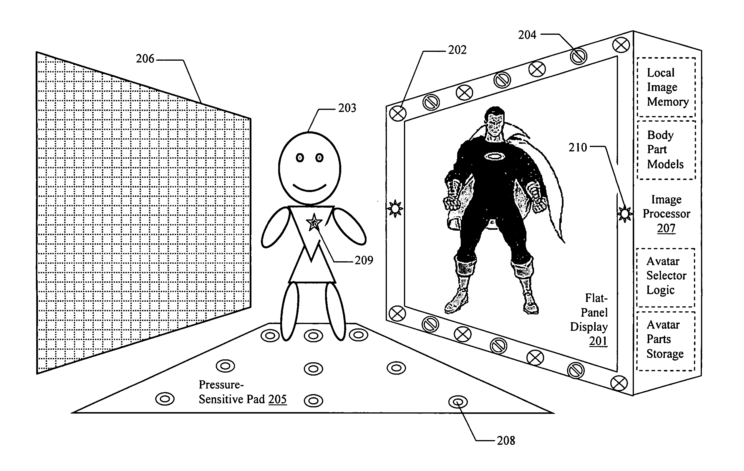
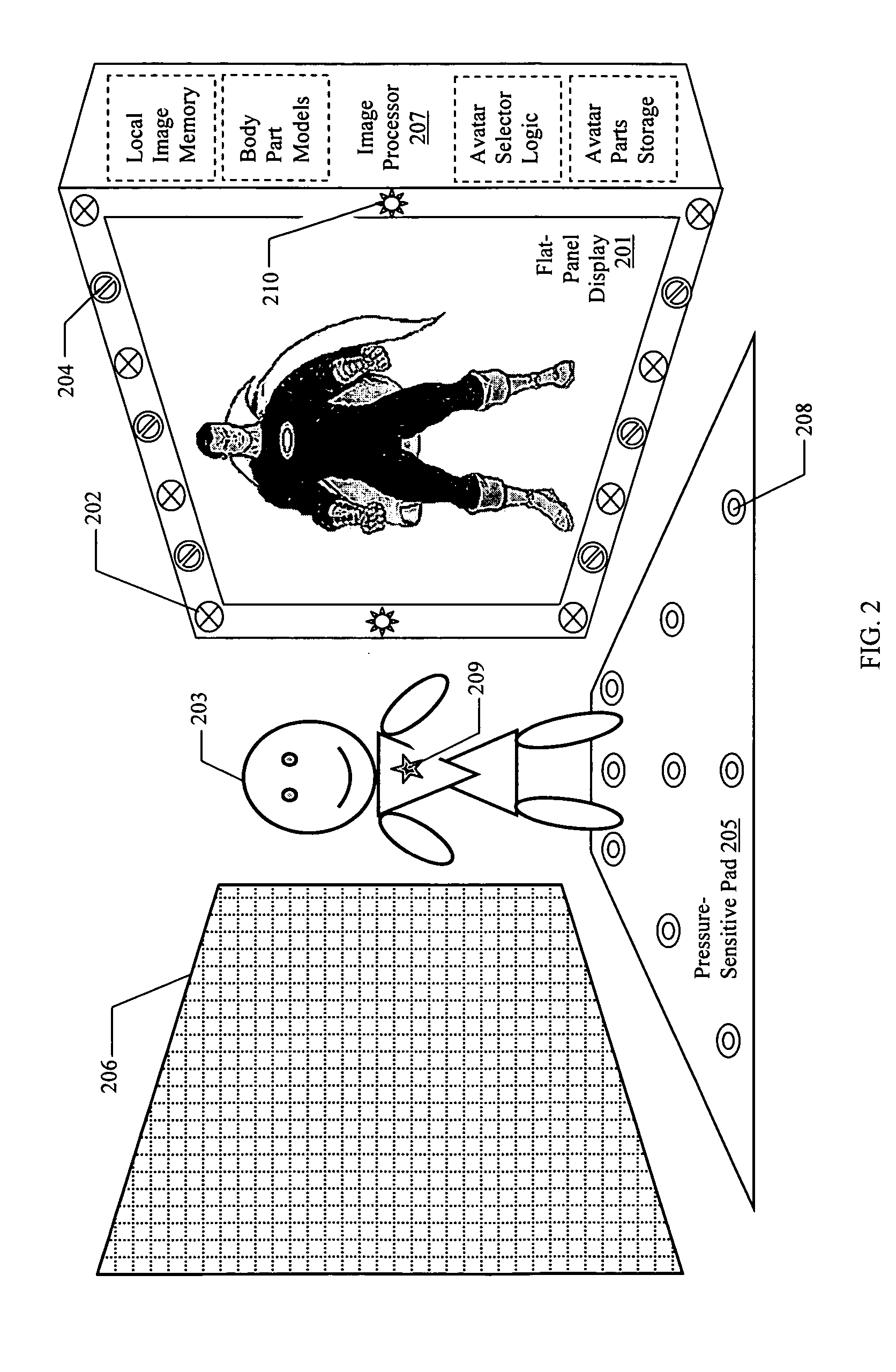
[0040] Third, one or more simple detection mechanisms may be employed to create a “mask” to separate the background from the subject(s) within the “active” foreground area of the invention. This mechanism provides the means for ignoring any objects at a greater than programmable distance as part of the “background”. To discourage physical contact with the display surface, it may also ignore objects at less than some minimum distance. This mechanism may employ a simple ultra-sonic ranging sensor array mounted within the display unit. Ultra-sonic or optical (visible and/or infrared) “image” capture sensors placed orthogonal to the display surface in a field within a fixed range of said surface may also be used to detect the body or bodies of interest. A pressure-sensitive surface may also be placed in front of t...
Problems solved by technology
In such cases, this alteration is generally considered to be an unwanted by-product of the mirror's construction.
Creating these imaginative characters is accomplished by time-consuming off-line processing before the images are transferred to film for display.
Inevitably, limited recognition of some basic movements such as hand and body movements (e.g., “jump”) will eventually be used to control the game.
None, however, are directed toward or appropriate to the real-time capturing of the entire human form for graphic manipulation and reproduction.
However, these methods only allow the selection of one of a predefined set of facial or full-body graphic icons using manual input denoting the intended expression or attitude, and are unrelated to the task of recognizing a human form and generating an avatar in real-time to mimic that form.
Since each of these methods require the subject to wear a special “exo-skeleton” of targets, none are appropriate for the task of recognizing movement in arbitrary human forms positioned in front of the current invention.
Method used
Image
Click on the blue label to locate the original text in one second.
Reading with bidirectional positioning of images and text.
Examples
Embodiment Construction
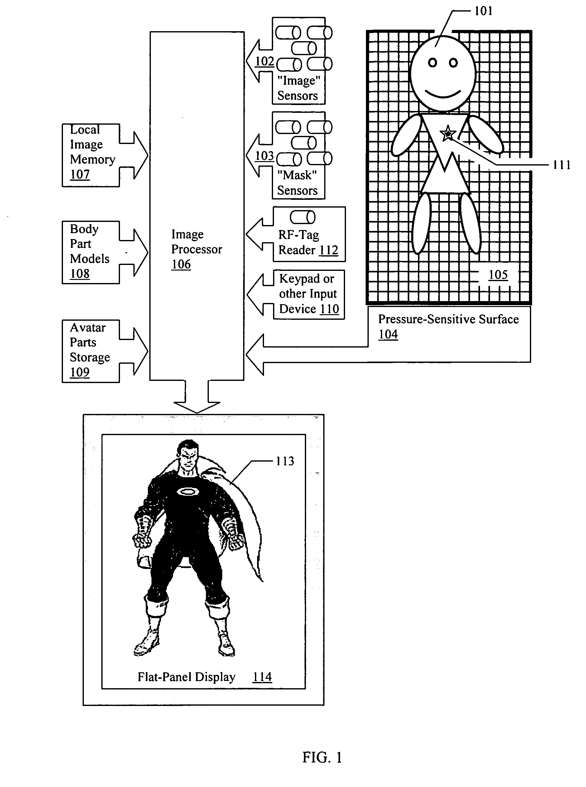
[0046] Referring first to FIG. 1, a subject (101) is positioned before the “image” sensors (102) and optional “mask” sensors (103) and on top of the optional pressure-sensitive pad (104). The latter set of sensors may be used to form an input “mask” with which to qualify the “image” data acquired by the subject sensors. This “mask” would represent all objects within the desired “foreground” range of the system. This qualification would allow the “image” data to discard any objects beyond this range as part of the “background”. An optional panel (105) with a color scheme and / or pattern chosen to aid in the discrimination of the edges of subject body parts may be positioned parallel to, and at a distance from, the display surface so that the subjects are between that surface and the display panel.
[0047] The data are applied to the image processor (106) where the raw “image” data is qualified by the “mask” as appropriate, in order to eliminate the “background” from the complete image....
PUM
Abstract
The mirror of the present invention provides a new device and method for generating a “reflection” of an object that may be processed before display. The invention comprises an image-capture system, an image-processor and a flat-panel display. By this combination, the invention is capable of acquiring the image of a subject in front of the display by passive means not requiring transmitters or reflectors on the subject (such means including optical, ultra-sonic, and electromagnetic sensors), processing the image in programmable ways to create an altered image of the subject and displaying the new image, which appears to mimic the movement and orientation of the original subject.
Description
[0001] Claims priority benefit of U.S. Provisional Application 60 / 236,183 filed on Sep. 29, 2000 Claims priority benefit of U.S. Non-Provisional Application 09 / 962,548 filed on Aug. 21, 2001REFERENCES [0002] U.S. PATENT DOCUMENTS [0003] U.S. Pat. No. 5,987,456 filed on Nov. 16, 1999 by, Ravela, et al. . . 707 / 5 [0004] U.S. Pat. No. 5,987,154 filed on Nov. 16, 1999 by Gibbon, et al. . . . 382 / 115 [0005] U.S. Pat. No. 5,982,929 filed on Nov. 9, 1999 by Ilan, et al. . . 382 / 200 [0006] U.S. Pat. No. 5,982,390 filed on Nov. 9, 1999 by Stoneking, et al. . . 345 / 474 [0007] U.S. Pat. No. 5,983,120 filed on Nov. 9, 1999 by Groner, et al. . . 600 / 310 [0008] U.S. Pat. No. 5,978,696 filed on Nov. 2, 1999 by VomLehn, et al. . . 600 / 411 [0009] U.S. Pat. No. 5,977,968 filed on Nov. 2, 1999 by Le Blanc . . . 345 / 339 [0010] U.S. Pat. No. 5,969,772 filed on Oct. 19, 1999 by Saeki . . . 348 / 699 [0011] U.S. Pat. No. 5,963,891 filed on Oct. 5, 1999 by Walker, et al. . . 702 / 150 [0012] U.S. Pat. No. 5,96...
Claims
Application Information
Patent Timeline
Application Date:The date an application was filed.
Publication Date:The date a patent or application was officially published.
First Publication Date:The earliest publication date of a patent with the same application number.
Issue Date:Publication date of the patent grant document.
PCT Entry Date:The Entry date of PCT National Phase.
Estimated Expiry Date:The statutory expiry date of a patent right according to the Patent Law, and it is the longest term of protection that the patent right can achieve without the termination of the patent right due to other reasons(Term extension factor has been taken into account ).
Invalid Date:Actual expiry date is based on effective date or publication date of legal transaction data of invalid patent.

