Color image forming apparatus using registration marks

a color image and registration mark technology, applied in the field of color image forming apparatus, can solve the problems of inability to detect the edge of the color registration mark with a good reproducibility, difficulty in ensuring the signal difference between the toner surface and the substrate surface, and inability to achieve good reproducibility. the effect of good accuracy

Inactive Publication Date: 2005-09-22
KONICA CORP
View PDF2 Cites 28 Cited by
  • Summary
  • Abstract
  • Description
  • Claims
  • Application Information

AI Technical Summary

Benefits of technology

[0015] Thus, this invention has solved the above-mentioned problems (1) and (2); its first object is to provide an image forming apparatus and an image forming method which makes it possible, even if the condition of use of the image transfer system changes with the passage of time, to detect exactly the proper position of mark images, and also makes it possible to adjust the forming positions of component color images with a good accuracy on the basis of position detection signals of high reliability.
[0016] Further, this invention has solved also the above-mentioned problems (3) and (4); its second object is to provide an image forming apparatus and an image forming method which makes it unnecessary, even if the condition of use of the image transfer system changes with the passage of time, to take trouble to form mark images avoiding belt scratches etc., and makes it possible, even if a plurality of scratches are produced on the image transfer system, to extract the positional data not influenced by the scratches for each of the component colors.

Problems solved by technology

Incidentally, according to a tandem-type color image forming apparatus based on a conventional method, there are problems as described below.
(1) In the color registration mark detection processing, owing to the change of the intermediate transfer belt 6 with the passage of time, for example, scratches on the belt surface, although they are different depending on the material of the belt, the reflected light quantity by the color toner layer is raised, which makes it difficult to secure sufficiently the signal difference between the toner surface and the substrate surface.
In particular, if the image density of the color registration marks CR fluctuates, that is, if the density becomes lower, or if the density becomes too much higher, the reflected light quantity becomes higher; therefore, there is a possible risk that the color registration marks cannot be detected with a good reproducibility due to the density fluctuation.
(3) If scratches (permanent scratches) increase on the belt owing to the change of the intermediate transfer belt (hereinafter referred to also as the image transfer system) with the passage of time, in the color registration mark detection processing, it occurs frequently the case where the sensors react to the scratches etc. on the belt, which makes it impossible to detect exactly the mark edge of the color registration marks.
However, as regards this method, in order to eliminate belt scratches etc. which appear unexpectedly, the above-mentioned processing has to be repeated plural times every occasion, it takes a considerable time for the calculation of the color deviation amounts of one time.

Method used


Image

  • Color image forming apparatus using registration marks
  • Color image forming apparatus using registration marks
  • Color image forming apparatus using registration marks

Examples


embodiment 1

(1) Embodiment 1

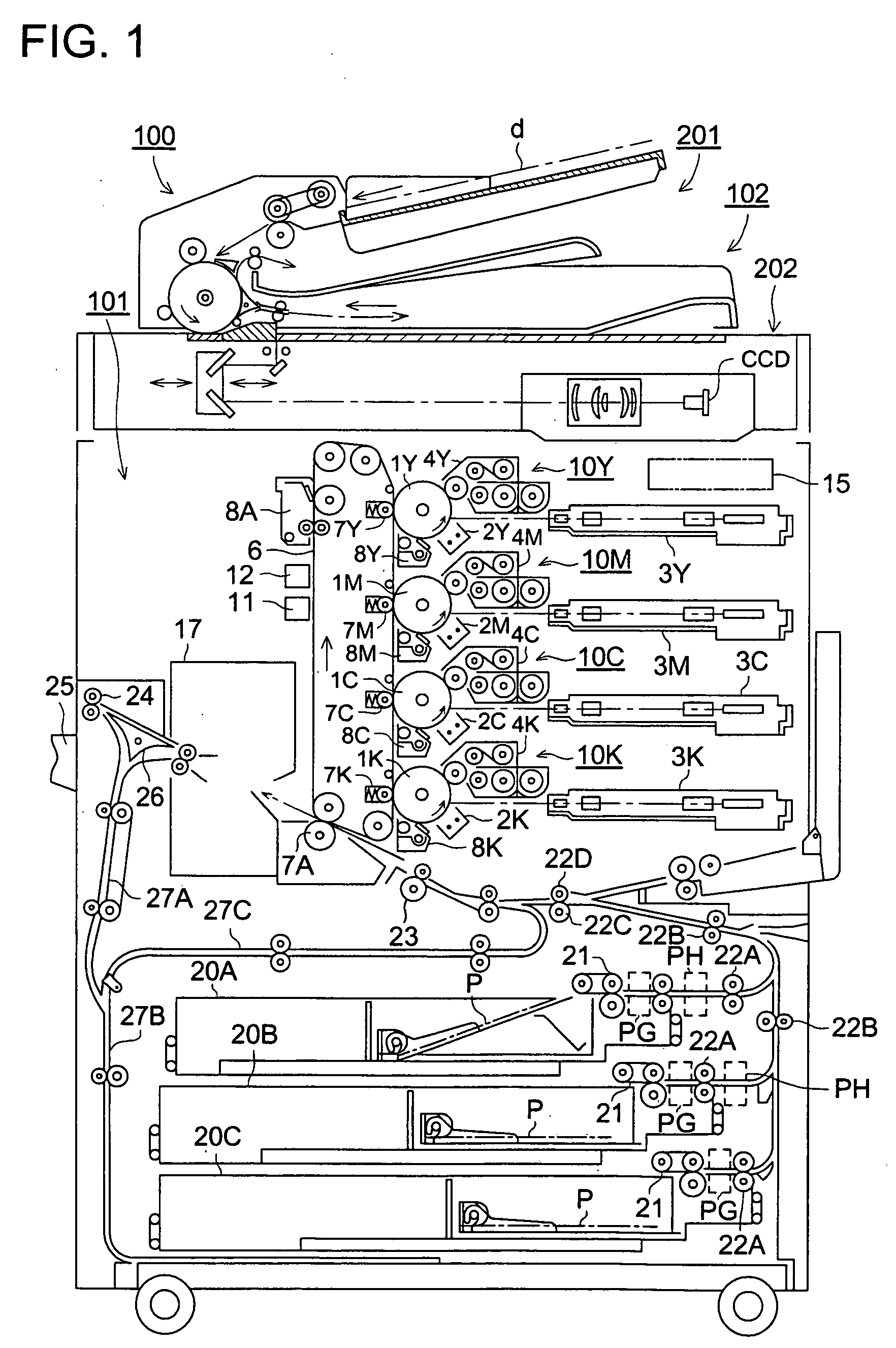
[0105]FIG. 1 is a conceptual drawing showing an example of the structure of a color image forming apparatus 100 as an example of the embodiment of this invention.

[0106] In this example of the embodiment, it is put into practice that there is provided a control device for controlling an image transfer means or a image forming unit on the basis of output signals of a density detection system and a position detection system for a color image, wherein the density of patch images for color density correction is detected by the position detection system for a color image, and a binarization reference value (also called a control reference value) for the detection of the positions of mark images is corrected on the basis of the density detection signal of the patch images outputted from said position detection system. Thus, even if the condition of use of the image transfer means has changed with the passage of time due to the change of reflected light quantity at the imag...

embodiment 2

(2) Embodiment 2

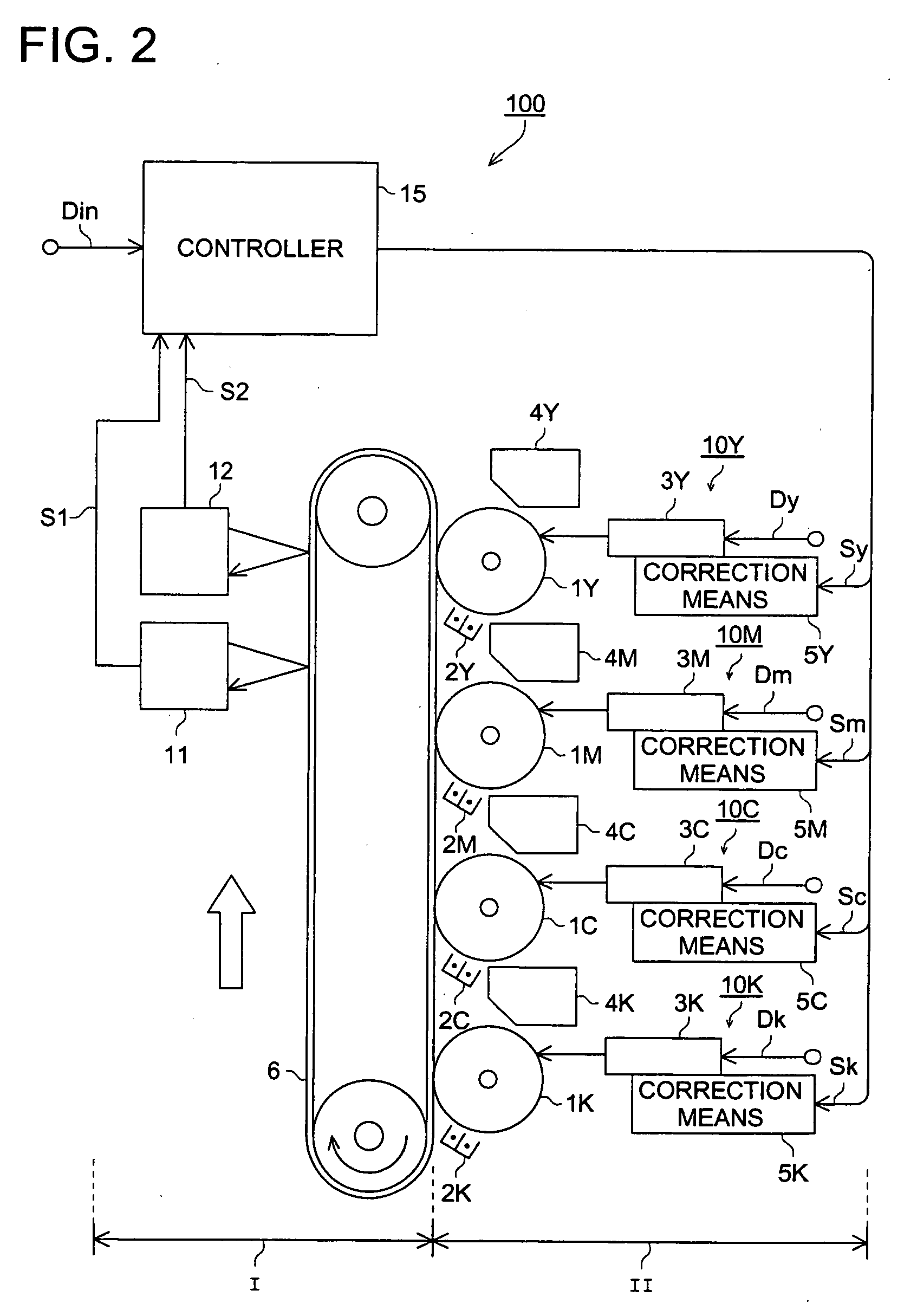
[0179]FIG. 12 is a block drawing showing an example of the structure of the image transfer system and the image forming system of a color image forming apparatus 200 as the embodiment 2 of the present invention.

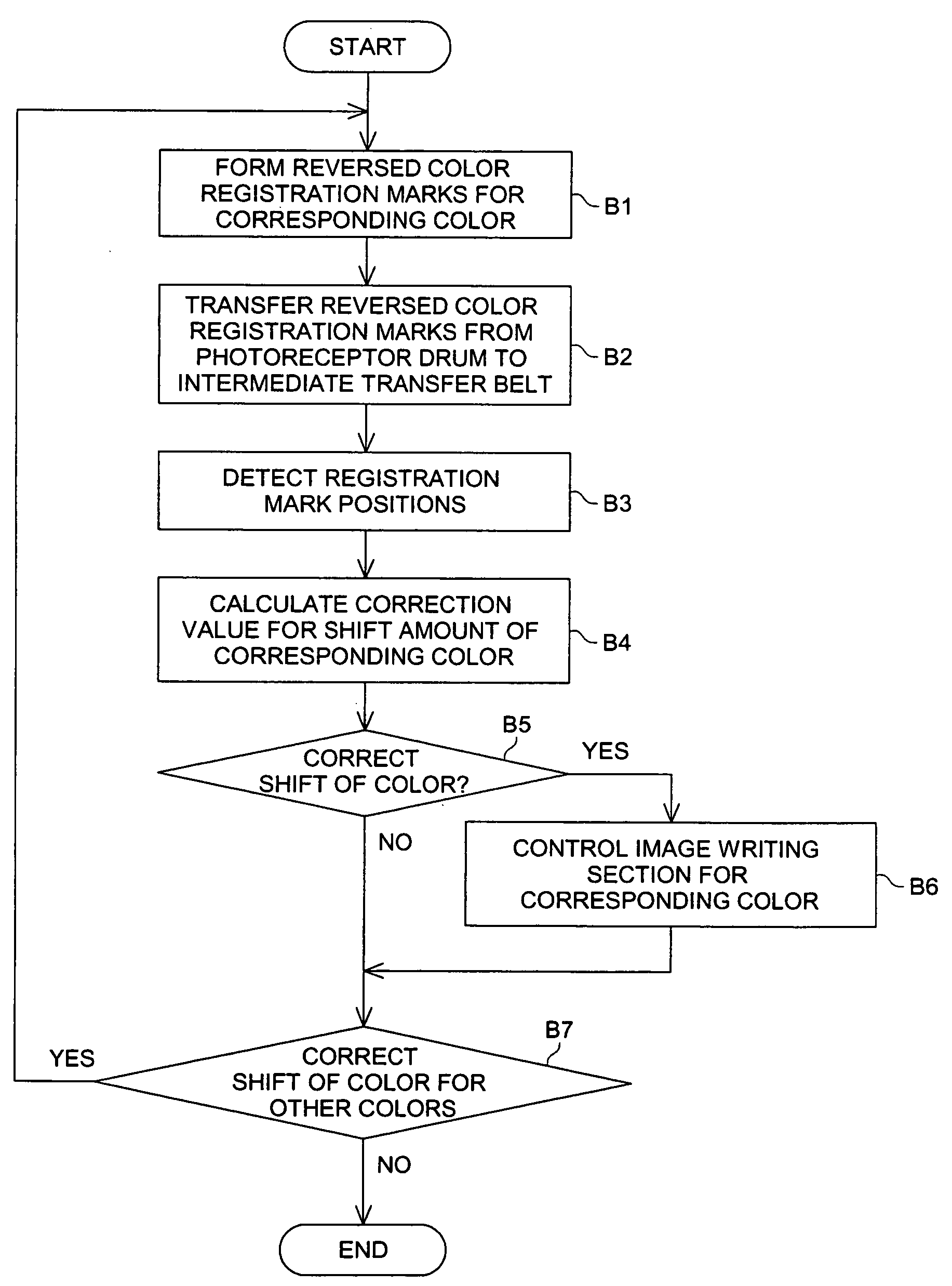
[0180] In this example of the embodiment, it is put into practice that, in order that a color image may be formed through the superposition of component color images on the basis of arbitrary image information, there is provided a control device 15 for controlling an intermediate transfer belt 6 and image forming units 10Y, 10M, 10C, and 10K on the basis of reversed mark images as the reversed ones of mark images for the registration of component color images, and at least, reversed mark images are formed beforehand on the intermediate transfer belt 6, and after that, the forming positions of component color images are adjusted on the basis of the position detection of mark images defined by the void portions of these reversed mark images. Thus, even if scrat...

embodiment 3

(3) Embodiment 3

[0220]FIG. 16 is a block drawing showing an example of the structure of the image transfer system and the image forming system of a color image forming apparatus 300 as the embodiment 3 of the present invention.

[0221] In this example of the embodiment, there is provided a control device 15 for controlling an intermediate transfer belt 6 and image forming units 10Y, 10M, 10C, and 10K on the basis of the position detection of mark images, mark images or reversed registration marks RCR obtained by reversing said mark images for the registration of component color images are formed on the intermediate transfer belt 6, and the image forming units 10Y, 10M, 10C, and 10K are controlled so as to adjust the forming positions of component color images on the basis of the position detection of non-reversed mark images or mark images defined by the void portions of reversed color registration marks formed on the intermediate transfer belt 6.

[0222] Owing to this, in the case wh...


PUM


Abstract

In an image forming apparatus for forming a color image by superposing component color images, a control device obtains position data representing a forming position of each of plural registration mark images for the component color images with respect to a positional reference value arbitrarily determined, divides the position data into each of a unit reference range representing a range in which one mark image is formed, converts the position data divided for each unit reference range into those based on respective reference values representing the front edge of the unit reference ranges, extracts the position data representing ranges common to the mutually overlapping ranges each of which is represented by a couple of position data corresponding to the rising and falling edges of a passage timing pulse as read position data of the mark image of the component color, and calculates the amounts of positional deviations of the component color images from one another on the basis of the position data extracted.

Description

CROSS-REFERENCE TO RELATED APPLICATIONS [0001] The present application is a Divisional application of U.S. application Ser. No. 10 / 435,743, filed on May 8, 2003, which claims the benefit of priority of JP 2002-140431, filed on May 15, 2002, and JP 2002-166142, filed on Jun. 6, 2002.BACKGROUND OF THE INVENTION [0002] This invention relates to a color image forming apparatus such as a tandem-type color printer or copying machine and a complex machine of these having an intermediate transfer belt or a photoreceptor belt and an image forming method suitably applied thereto. [0003] In recent years, a tandem-type color printer or copying machine or a complex machine of these has been used in many cases. In these color image forming apparatus, there are provided exposure means, developing devices, and photoreceptor drums for the respective colors of yellow (Y), magenta (M), cyan (C), and black (BK), an intermediate transfer belt, and a fixing device. [0004] For example, in the exposure mea...

Claims


Application Information

Patent Timeline
Patent Type & Authority Applications(United States)
IPC IPC(8): B41J29/393G03F3/08G03G15/01G06F15/00G06K15/12H04N1/50
CPCB41J29/393G03G2215/0119G03G15/0194G06K15/129H04N1/506G03G2215/0161
Inventor NISHIKAWA, EIJIMARUYAMA, HIROYUKIARAIMOTOI, TOSHIHIROIZUMIYA, KENJIOKUTOMI, RYUJIKISHI, SHINOBUOGATA, SATOSHIOZAWA, KENICHIUEDA, TADAYUKIHIGASHI, YUMIKO
Owner KONICA CORP
Why Eureka
Try Eureka