Tape Guide decreasing transverse movement of data storage tape at high frequencies

a technology of data storage tape and guide, which is applied in the direction of data recording, record carrier guidance, instruments, etc., can solve the problems of data storage tape damage, stiction is especially strong, and guide compliant often has problems of its own

Inactive Publication Date: 2005-09-22
IMATION
View PDF12 Cites 18 Cited by
  • Summary
  • Abstract
  • Description
  • Claims
  • Application Information

AI Technical Summary

Benefits of technology

[0008] One aspect of the present invention relates to a tape guide for use with a data storage tape system including a read / write head. The tape guide includes a bearing portion and a tape interface portion extending from the bearing portion. The tape interface portion is configured to support a data storage tape near the read / write head. Upon longitudinal movement of the data storage tape across the tape interface portion, the tape guide limits a spectral content of data storage tape lateral movement measured at the read / write head to less than 0.1 μm at lateral movement frequencies between 50 and 500 cycles / meter.
[0009] Another aspect of the present invention relates to a data storage tape system including a read / write head, a first tape guide, and a second tape guide. The first tape guide is spaced from the read / write head. The second tape guide is spaced from the read / write head opposite the first tape guide. The first and second tape guides are configured to support a data storage tape near the read / write head. Upon longitudinal movement of the data storage tape across the first and second tape guides, the first and second tape guides limit a spectral content of the data storage tape lateral movement measured at the read / write head to less than 0.1 μm at lateral movement frequencies between 50 and 500 cycles / meter.
[0010] Another aspect of the present invention relates to a method of controlling error in reading from or writing to a data storage tape. The method includes providing a first tape guide spaced from a read / write head and a second tape guide spaced from the read / write head opposite the first tape guide, supporting the data storage tape between the first and a second tape guide as the data storage tape passes the read / write head, and longitudinally moving the data storage tape across the tape guides and the read / write head. The method further includes limiting a spectral content of the data storage tape lateral movement measured at the read / write head to less than 0.1 μm at lateral movement frequencies between 50 and 500 cycles / meter.

Problems solved by technology

However, when the data storage tape is stopped and rests on the channel guides under tension, the data storage tape often sticks to the channel guide.
Such stiction makes the initiation of data storage tape movement difficult and may result in damage to the data storage tape or in data storage tape drive failure due to the inability of the data storage tape drive to start data storage tape motion.
Stiction is especially a problem with stationary channel guides in hot and / or wet environments.
Compliant guides often have problems of their own, such as spring vibration.
Although the flanges constrain transverse movement, the edges of the data storage tape may contact the flanges causing a shock to the system forcing the data storage tape to quickly vacillate between the two flanges, thereby inducing high-frequency transverse movement to the data storage tape.
Although servo systems, such as the servo system described above, are adept in tracking transverse movement of the data storage tape at low frequencies (i.e., relatively low speed of transverse movement), servo tracking systems often are unable to keep up with similar amplitudes of transverse movement when the transverse movement occurs at a relatively high frequency.
As such, when the data storage tape contacts a flange, the induced high frequency causes additional read / write errors since the transducer head is unable to closely track the tape and read from the data tracks.
In other words, even where the amplitude of transverse movement is limited by the channel, compliant, or typical rotating guides with flanges, the increased frequency often is too much for even a transducer head utilizing servo tracking to account for.

Method used


Image

  • Tape Guide decreasing transverse movement of data storage tape at high frequencies
  • Tape Guide decreasing transverse movement of data storage tape at high frequencies
  • Tape Guide decreasing transverse movement of data storage tape at high frequencies

Examples


Embodiment Construction

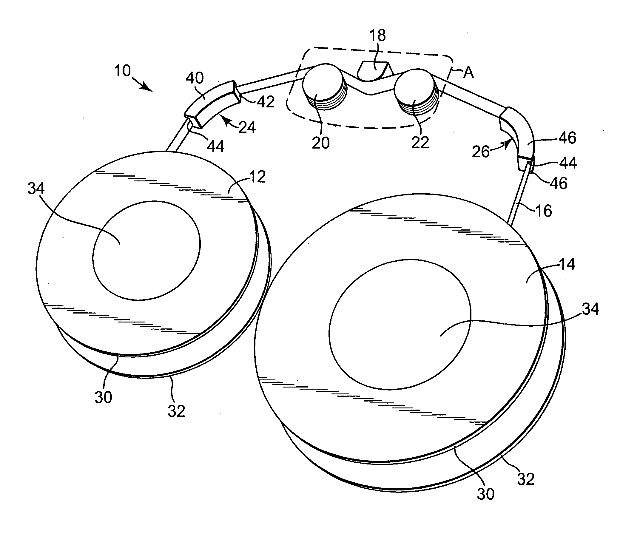
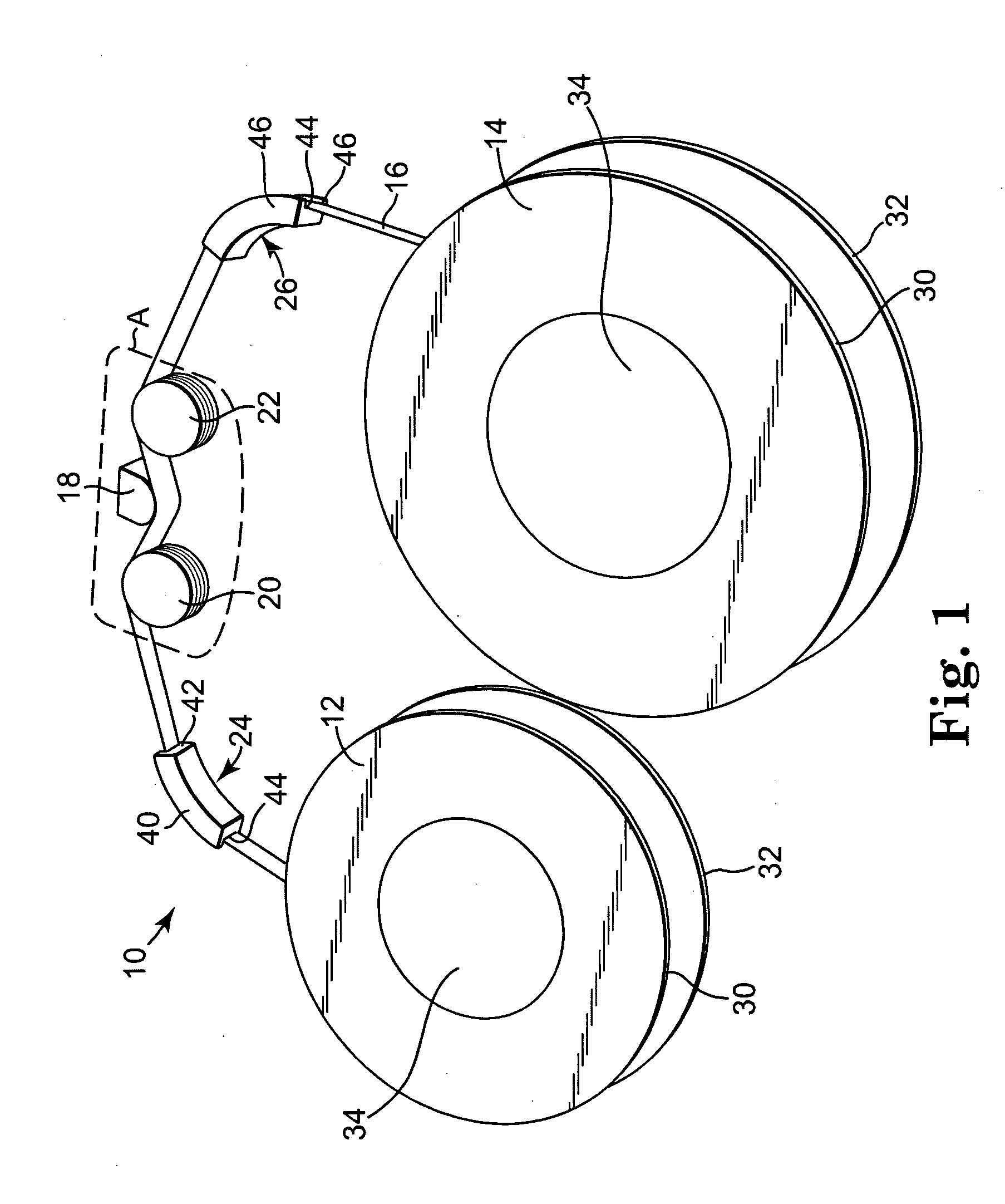
[0023] An exemplary data storage tape system 10 according to one embodiment of the present invention is generally illustrated in FIG. 1. The data storage tape system 10 includes a first tape reel 12, a second tape reel 14, a data storage tape 16, a transducer or read / write head 18, a first tape guide 20, and a second tape guide 22. The data storage tape 16 is wound about and extends between the first and second tape reels 12 and 14. In particular, a tape path is defined whereby the data storage tape 16 extends from the first tape reel 12 over the first tape guide 20, past the read / write head 18, over the second tape guide 22, and finally to the second tape reel 14. In one embodiment, the data storage tape system 10 optionally includes a first collateral tape guide 24 and a second collateral tape guide 26 to support the data storage tape 16. The first collateral tape guide 24 is positioned between the first tape reel 12 and the first tape guide 20, and the second collateral tape guid...


PUM

PropertyMeasurementUnit
velocityaaaaaaaaaa
velocityaaaaaaaaaa
radiusaaaaaaaaaa

Abstract

A tape guide for use with a data storage tape system including a read/write head. The tape guide includes a bearing portion and a tape interface portion extending from the bearing portion. The tape interface portion is configured to support a data storage tape near the read/write head. Upon longitudinal movement of the data storage tape across the tape interface portion, the tape guide limits a spectral content of data storage tape lateral movement measured at the read/write head to less than 0.1 μm at lateral movement frequencies between 50 and 500 cycles/meter.

Description

THE FIELD OF THE INVENTION [0001] The present invention generally relates to tape guides for use with data storage tape. More particularly, the present invention relates to tape guides configured to limit transverse movement of the data storage tape at relatively high frequencies. BACKGROUND OF THE INVENTION [0002] Magnetic media are a popular form of data storage media, and are used for storage and retrieval of data. Magnetic media come in many forms, such as data storage tapes and data storage disks. A read / write head assembly, which includes one or more read / write transducer heads, writes data to and reads data from the magnetic medium. Data stored in the medium are usually organized into “data tracks,” and the transducer head writes data to and reads data from the data tracks. Data tracks and magnetic tape are generally parallel to each other, and often are orientated substantially longitudinally on the tape. [0003] Typically, the data storage tape incorporating the data tracks ...

Claims


Application Information

Patent Timeline
Patent Type & Authority Applications(United States)
IPC IPC(8): G11B5/09G11B15/18G11B15/60G11B17/00G11B19/02
CPCG11B15/602
Inventor JOHNSON, DOUGLAS W.
Owner IMATION
Why Eureka
Try Eureka