Method and apparatus for multicast packet readout control

a multicast packet and control technology, applied in the field of multicast packet readout control, can solve problems such as unsatisfactory packet loss

Inactive Publication Date: 2005-09-22
FUJITSU LTD
View PDF49 Cites 101 Cited by
  • Summary
  • Abstract
  • Description
  • Claims
  • Application Information

AI Technical Summary

Benefits of technology

[0067] The present invention was conceived to overcome the above-described problems in the prior art, and it is an object of the present invention to provide a multicast packet readout control technique that...

Problems solved by technology

The multicast packet (PACKET i) is d...

Method used


Image

  • Method and apparatus for multicast packet readout control
  • Method and apparatus for multicast packet readout control
  • Method and apparatus for multicast packet readout control

Examples


Embodiment Construction

[0097] The preferred embodiments of the present invention are now described below with reference to the attached drawings.

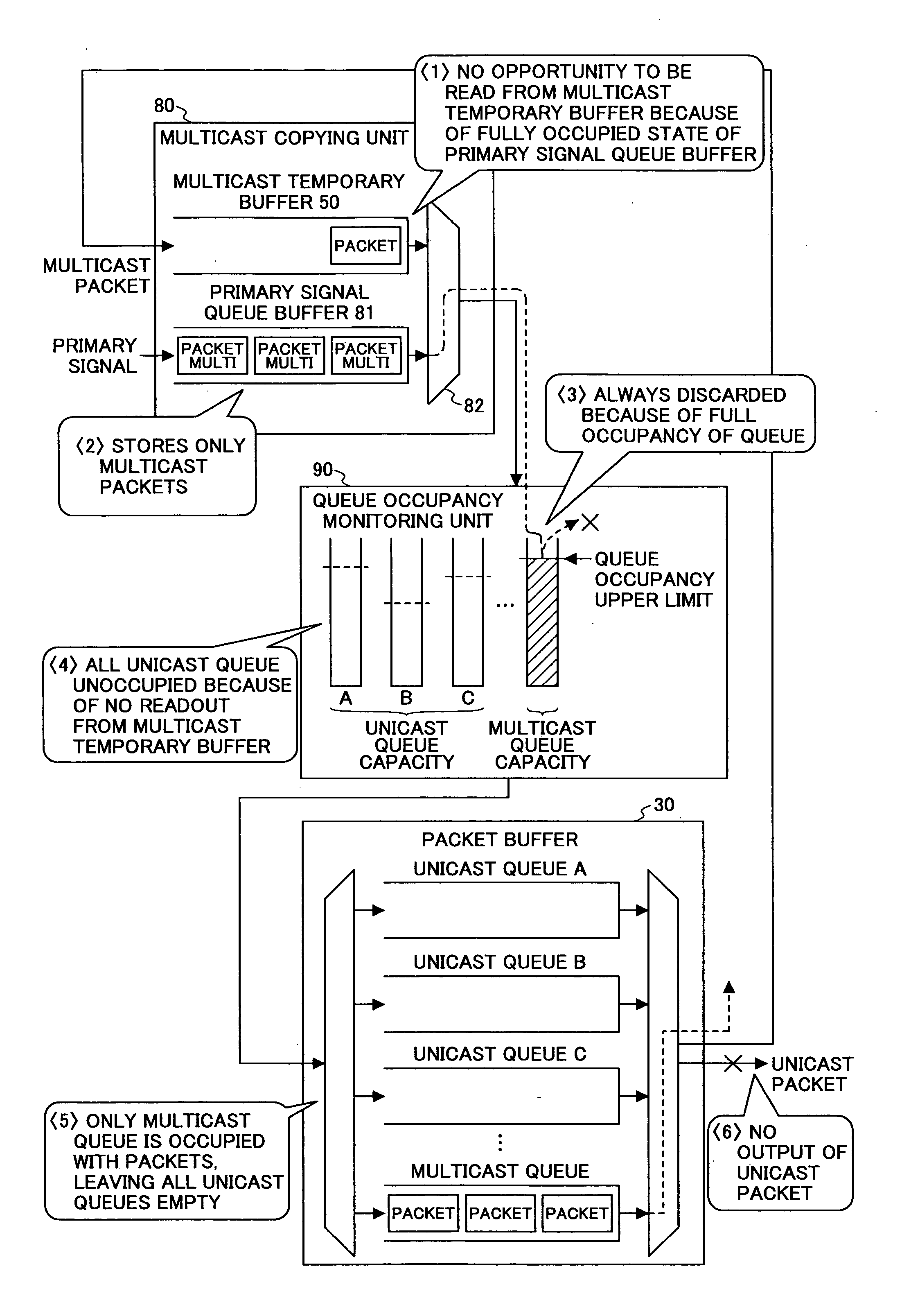
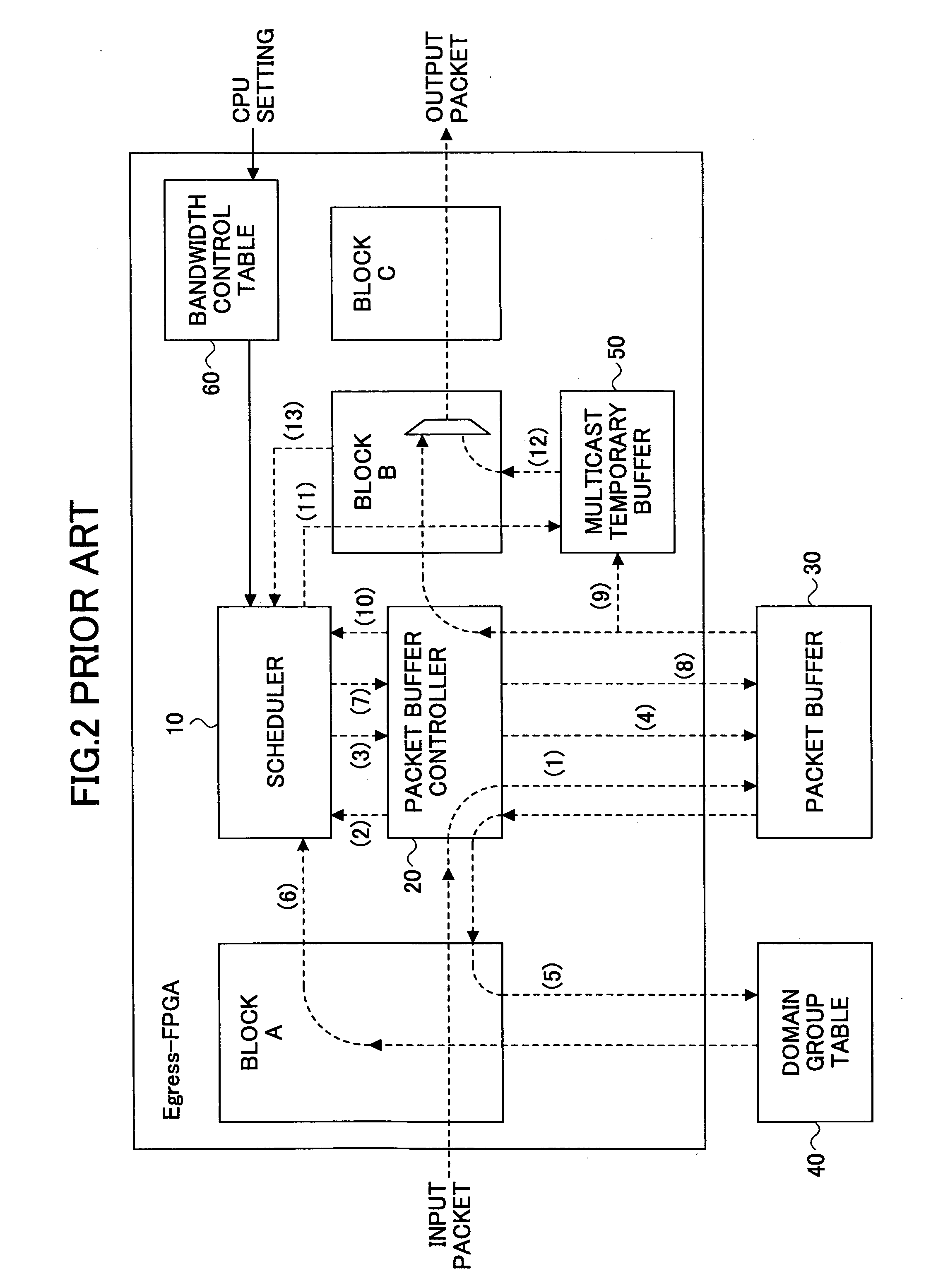
[0098]FIG. 6 is a functional block diagram illustrating the configuration of multicast packet readout control according to an embodiment of the invention. The same components as those of the conventional structure shown in FIG. 4 are denoted by the same numerical references, and explanation for them is omitted. Explanation is made below with a focus on the difference from the conventional art. The queue structure of the packet buffer 30 shown in both FIG. 4 and FIG. 6 is based on the priority classes.

[0099] The first difference between the present invention and the conventional art is the output route of a multicast packet read from the multicast temporary buffer 50. In the conventional technique, the multicast packet read from the multicast temporary buffer 50 is output via a selector 70 to the destination. In contrast, in an embodiment of the present inventio...


PUM


Abstract

A multicast packet readout control method is disclosed. An input multicast packet is temporarily stored in a multicast queue of a packet buffer. The multicast packet is read from the multicast queue, and converted into a unicast packet addressed to each of the destinations of the multicast packet. The converted unicast packet is stored in a unicast queue of the packet buffer. The converted unicast packet is then read from the unicast queue and transmitted to the destination.

Description

BACKGROUND OF THE INVENTION [0001] 1. Field of the Invention [0002] The present invention generally relates to a method and an apparatus for multicast packet readout control, and more particularly, to a technique for reading and transmitting packets from a packet buffer, while performing QoS (Quality of Service) processing (including bandwidth control and priority routing control), in a layer 2 switch in IP (Internet Protocol) network. The packet buffer temporarily stores packets, such as Ether (registered trademark) frames, for each destination. [0003] 2. Description of the Related Art [0004] A unicast packet addressed to a single destination is read from a packet buffer and transmitted to the destination. For a multicast packet with multiple destinations, the packet read from the packet buffer has to be copied as many as the number of destinations so as to be transmitted to each of the destinations. [0005] To identify the destinations of a multicast packet, a destination bitmap is...

Claims


Application Information

Patent Timeline
IPC IPC(8): H04J1/16H04J3/14H04L1/00H04L12/18H04L12/28H04L47/22H04L47/32
CPCH04L12/18H04L12/5693H04L47/15H04L47/30H04L47/32H04L49/254H04L47/621H04L47/6215H04L47/6225H04L49/201H04L47/522H04L47/50
Inventor OGAWA, MASAYUKIMIURA, KENJIMATSUO, TAMOTSUURANO, HIROSHI
Owner FUJITSU LTD
Why Eureka
Try Eureka