Noise shaped interpolator and decimator apparatus and method

a decimator and interpolator technology, applied in the field of radio frequency signals, can solve the problems of reducing the robustness of the interpolator device as a whole, reducing the robustness of the interpolator device, and prior art solutions that do not provide the ability to dynamically adapt the operation of the interpolator (or the decimator) as a function of operational conditions or parameters, so as to reduce the presence of phase noise and suppress phase noise

Active Publication Date: 2005-09-22
STMICROELECTRONICS SRL
View PDF16 Cites 27 Cited by
  • Summary
  • Abstract
  • Description
  • Claims
  • Application Information

AI Technical Summary

Benefits of technology

[0017] In a fourth aspect of the invention, a method of suppressing phase noise in a radio frequency device having a transmit frequency and receive frequency is disclosed. In one embodiment, the method comprises: providing a delta-sigma Frac-N phase lock loop (P

Problems solved by technology

The prior art solutions, however, have several drawbacks associated therewith.
This PLL arrangement is costly in terms of additional complexity and power consumption.
It also reduces the robustness of the interpolator device as a whole.
Additionally, prior art solutions do not provide the ability to dynamically adapt the operat

Method used


Image

  • Noise shaped interpolator and decimator apparatus and method
  • Noise shaped interpolator and decimator apparatus and method
  • Noise shaped interpolator and decimator apparatus and method

Examples


Embodiment Construction

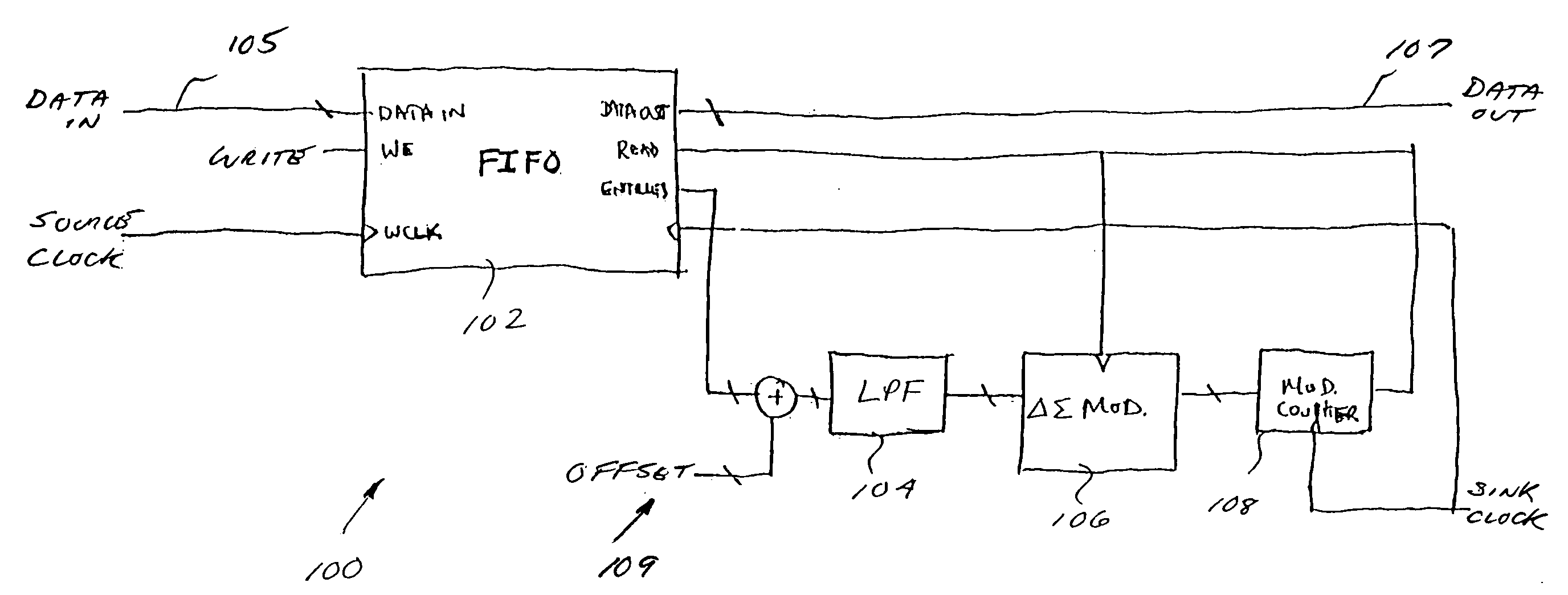
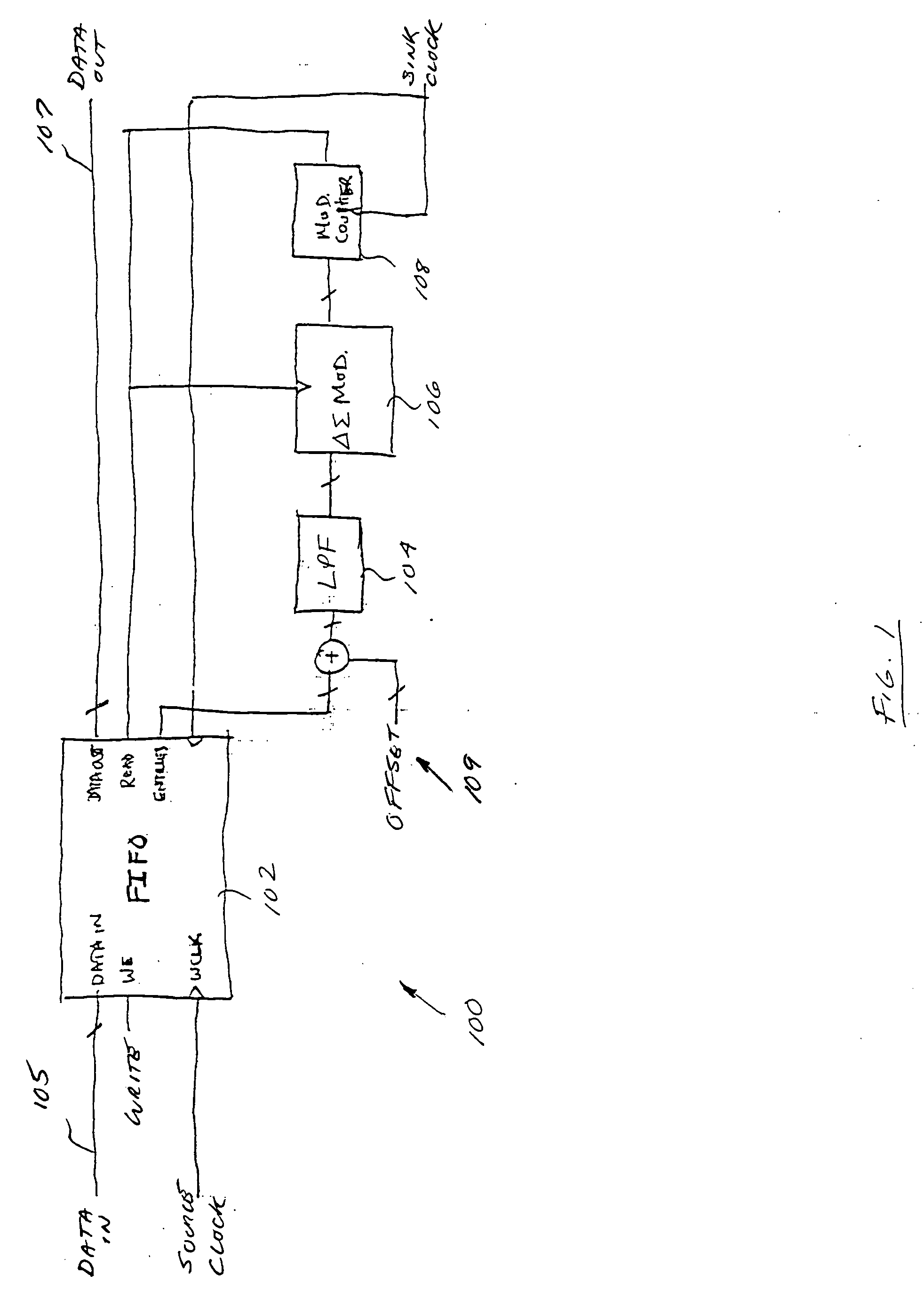
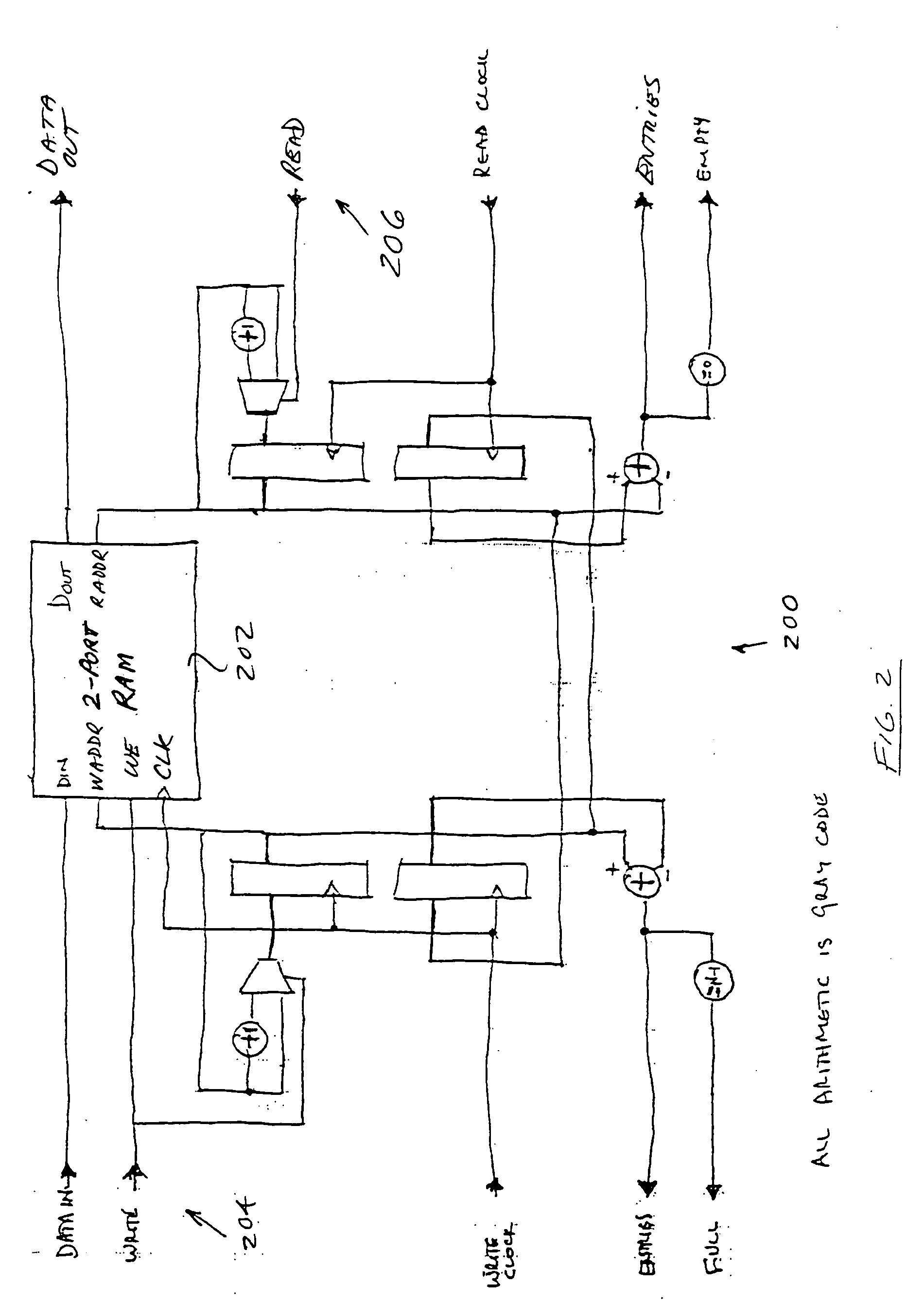
[0040] Reference is now made to the drawings wherein like numerals refer to like parts throughout.

[0041] As used herein, the term “code division multiple access,” or CDMA, generally refers to digital wireless technology that uses a spread spectrum technique to disperse a signal across a wide range of frequencies, such as according to a pseudo-noise or other code.

[0042] As used herein, the terms “transmit”, “transmission”and “transmitting” for convenience may generally be considered to refer to both the acts of transmitting signals and receiving signals, as applicable.

[0043] As used herein, the term “processor” is meant generally to include all types of data or signal processing devices including, without limitation, digital signal processors (DSPs), reduced instruction set computers (RISC), general-purpose (CISC) processors, microprocessors, gate arrays (e.g., FPGAs), Reconfigurable Compute Fabrics (RCFs), and application-specific integrated circuits (ASICs). Such digital process...


PUM


Abstract

Improved interpolator and decimator apparatus and methods, including the addition of an elastic storage element in the signal path. In one exemplary embodiment, the elastic element comprises a FIFO which advantageously allows short term variation in sample clocks to be absorbed, and also provides a feedback mechanism for controlling a delta-sigma modulated modulo-N counter based sample clock generator. The elastic element combined with a delta-sigma modulator and counter creates a noise-shaped frequency lock loop without additional components, resulting in a much simplified interpolator and decimator.

Description

PRIORITY [0001] This application claims priority to U.S. Provisional Application Ser. No. 60 / 493,041 filed Aug. 5, 2003 and 60 / 496,320 filed Aug. 18, 2003 each entitled “NOISE SHAPED INTERPOLATOR AND DECIMATOR APPARATUS AND METHOD” and each incorporated herein by reference in its entirety.RELATED APPLICATIONS [0002] This application is related to co-owned and co-pending U.S. patent application Ser. No. 10 / 382,297 filed Mar. 4, 2003 and entitled “RESONANT POWER CONVERTER FOR RADIO FREQUENCY TRANSMISSION AND METHOD”, published on Feb. 26, 2004 as U.S. Patent Publication No. 20040037363, which claims priority benefit of U.S. provisional patent application Ser. No. 60 / 361,812 of the same title filed Mar. 4, 2002, and co-owned and co-pending U.S. patent application Ser. No. 10 / 382,326 filed Mar. 4, 2003 and entitled “CODER APPARATUS FOR RESONANT POWER CONVERSION AND METHOD” published on Nov. 20, 2003 as U.S. Patent Publication No. 20030216906, which claims priority benefit of U.S. provis...

Claims


Application Information

Patent Timeline
IPC IPC(8): H03H17/06H04L5/16H04L7/02
CPCH03H17/0614H03H17/0628H04L7/005H04L7/02H04L7/0008H03H2218/04H04L7/0025
Inventor NORSWORTHY, STEVEN R.REDGRAVE, JASON RUPERT
Owner STMICROELECTRONICS SRL
Why Eureka
Try Eureka