Wearable communication device
a communication device and wearable technology, applied in the direction of mechanical pattern conversion, electric/electromagnetic audible signalling, electric/electromagnetic transducers, etc., can solve the problems of not responding to a call, user cannot use the phone immediately, and sometimes the voice of the recipient is difficult to hear
- Summary
- Abstract
- Description
- Claims
- Application Information
AI Technical Summary
Benefits of technology
Problems solved by technology
Method used
Image
Examples
first embodiment
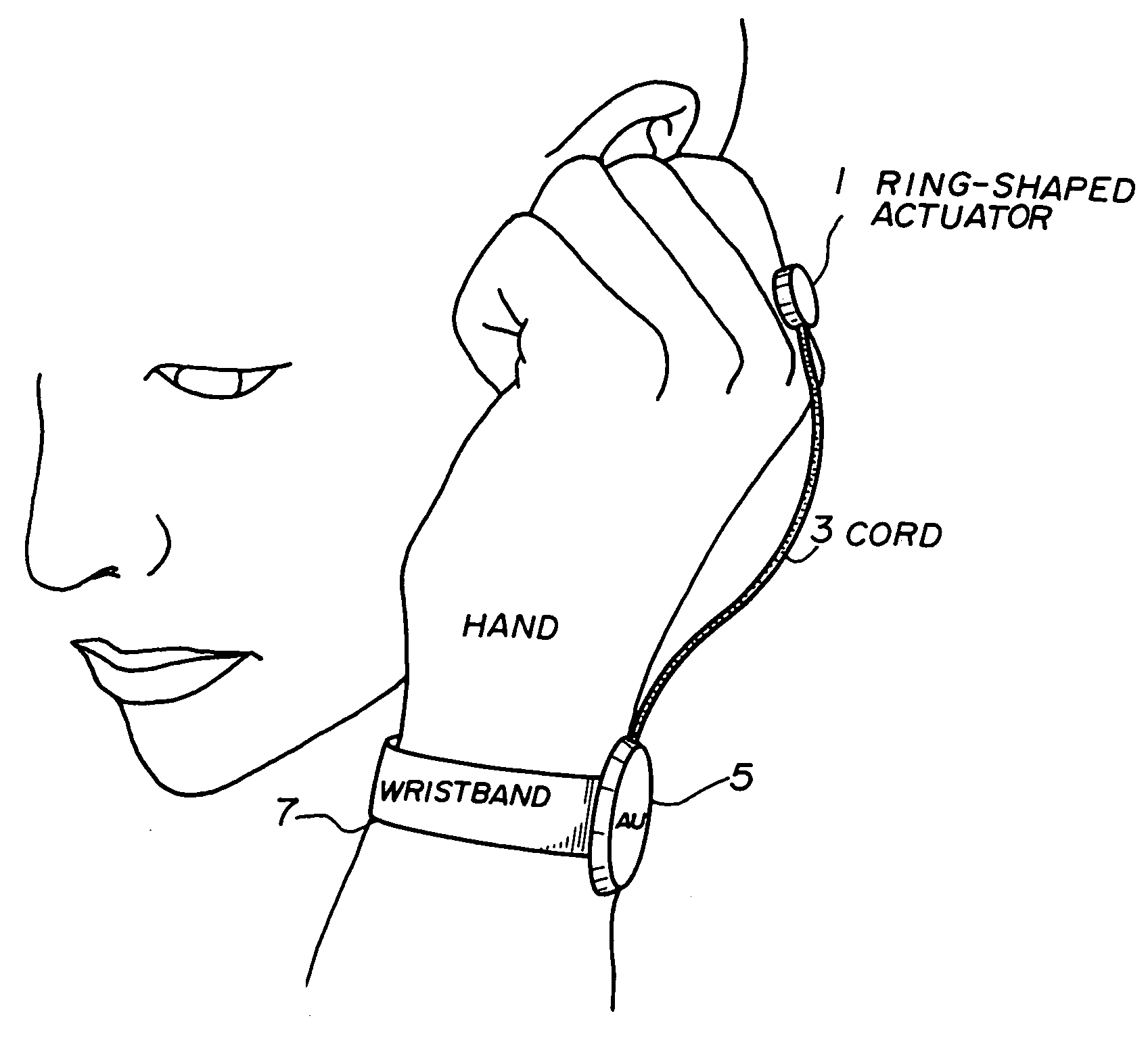
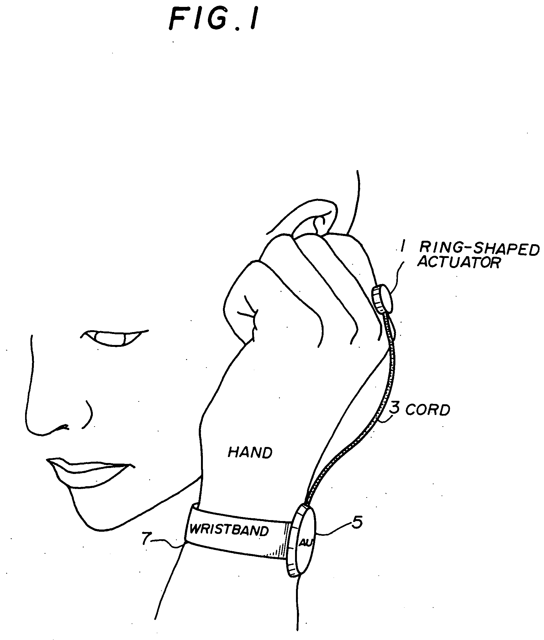
[0151]FIG. 1 is a schematic perspective diagram showing a wearable receiver of the present invention.
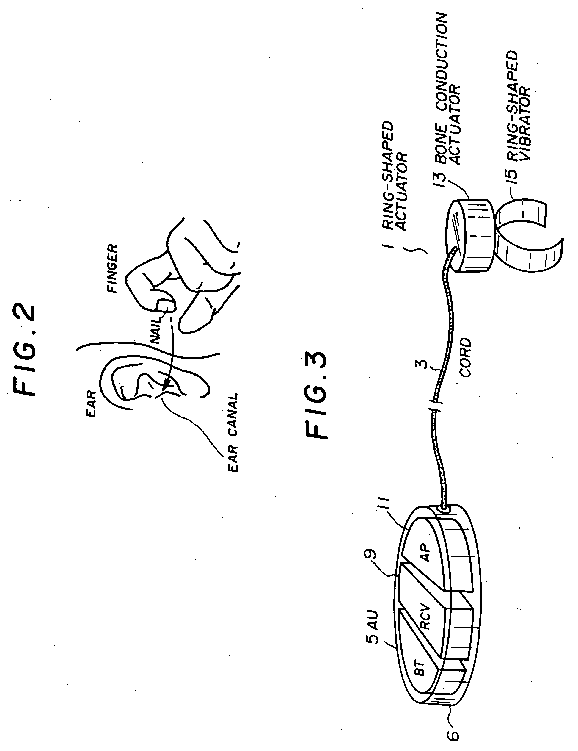
[0152] As shown in FIG. 1, the wearable receiver includes a ring-shaped actuator 1, a cord 3, an amp unit (AU) 5 and a wristband 7. The ring-shaped actuator 1 which has a ring-shaped vibrator and a bone conduction actuator is mounted on a base of the user's finger, and the amp unit (AU) 5 is mounted on the user's wrist with the wristband 7. When the user use the wearable receiver, as shown in FIG. 2, the user covers the ear canal with a fingernail or inserts a finger into the ear canal or touches the user's finger to a part near the user's ear.
[0153]FIG. 3 is a perspective view showing the inside of the wearable receiver in detail. As shown in the figure, the amp unit (AU) 5 includes a battery (BT) 6 for supplying power, a wireless receiver (RCV) 9 and an amp (AP) 11 for driving the bone conduction actuator. Hereinafter, the amp (AP) for driving the bone conduction actuator will be ...
second embodiment
[0158]FIG. 6 shows a wearable receiver of the present invention. As shown in FIG. 6, a connector 25 which is detachable from an actuator 23 is provided on the upper side of the actuator 23. A cord 27 connecting between an amp unit 29 and the actuator 23 can be stored in the amp unit (AU) 29.
[0159]FIG. 7 shows a sectional view of the connector (CN) 25 and the amp unit (AU) 29. FIG. 8 is a perspective diagram of the wearable receiver. As shown in FIG. 7, the amp unit 29 stores the cord 27 by wrapping it around the center part of the amp unit. Also, the connector 25 acts as a switch. To be more specific, a base (SWB) 31 of the connector can be inserted into an outlet (SWA) 33 of the case, and the switch is operated by connecting the SWA33 and the SWB31. The SWA33 forms a pair of electrodes, and the switch is realized by allowing the SWB31 to contact the pair of electrodes. The switch can be realized in various ways. For example, the SWA33 can be made of a Hall device and the SWB31 can ...
fourth embodiment
[0165]FIG. 13 is a schematic perspective diagram showing a wearable receiver of a As shown in (a) of the figure, the wearable receiver includes an amp unit (AU) 38 and a boom (BM) 40 which extends from the amp unit (AU) 38. An actuator (AC) 42 is provided at an end point of the boom (BM) 40. As shown in (b) of the figure, the part which contacts the back of the hand is shaped like a smooth dome which is downward convex, and the surface of which part is processed with teflon and the like so as to reduce friction. The amp unit (AU) 38 is mounted on the wrist by the wristband 44. Also, the wearable receiver has an ON / OFF switching mechanism using expansion and contraction of the boom (BM) 40. The boom (BM) 40 can be stored into the amp unit (AU) 38. FIG. 14 shows a case in which the boom is stored.
[0166] As shown in FIG. 13, when the user uses this wearable receiver, the user bends the hand backwards and brings the end of the boom into contact with the back of the hand, specifically, ...
PUM
 Abstract
Description
Claims
Application Information
 - R&D
- Intellectual Property
- Life Sciences
- Materials
- Tech Scout
- Unparalleled Data Quality
- Higher Quality Content
- 60% Fewer Hallucinations
Browse by: Latest US Patents, China's latest patents, Technical Efficacy Thesaurus, Application Domain, Technology Topic, Popular Technical Reports.
© 2025 PatSnap. All rights reserved.Legal|Privacy policy|Modern Slavery Act Transparency Statement|Sitemap|About US| Contact US: help@patsnap.com


