Method and device for safeguarding a hazardous area

a technology for hazardous areas and methods, applied devices for safeguarding hazardous areas, can solve the problems of not providing the reliability of detection required in the field of methods known to da

Inactive Publication Date: 2005-09-22
PILZ (COMPANY)
View PDF20 Cites 79 Cited by
  • Summary
  • Abstract
  • Description
  • Claims
  • Application Information

AI Technical Summary

Benefits of technology

[0009] Against this background, it is an object of the present invention to provide an improved method and a corresponding device which allow to safeguard a hazardous area with-out a large outlay on installation, but with adequate reliability.

Problems solved by technology

On their own, those methods known to date do not provide the reliability of detection required to ensure that the hazardous area of an automatically operating machine is reliably safeguarded.

Method used


Image

  • Method and device for safeguarding a hazardous area
  • Method and device for safeguarding a hazardous area
  • Method and device for safeguarding a hazardous area

Examples


Embodiment Construction

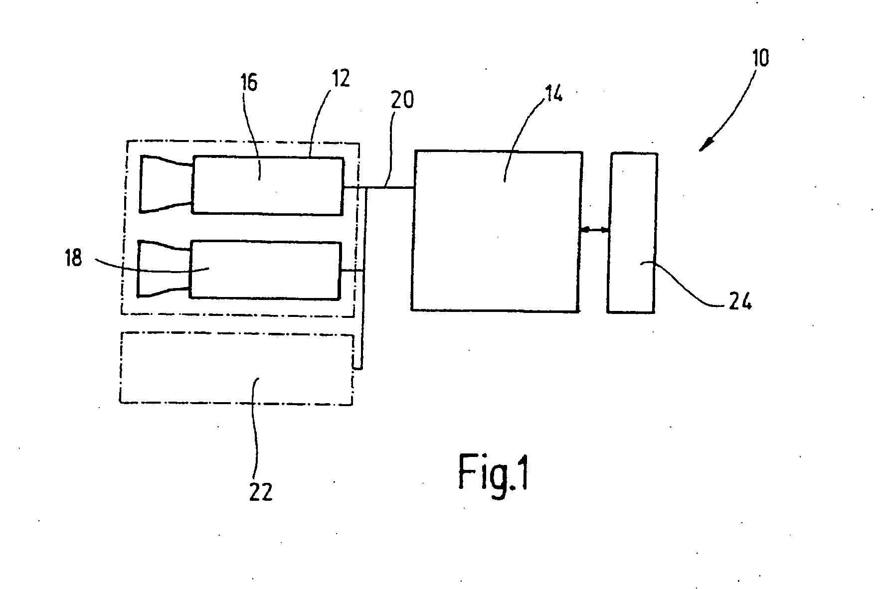
[0041] An embodiment of the inventive device is denoted in its entirety in FIG. 1 by reference numeral 10. The device 10 includes a camera module 12 and an evaluation unit 14. Illustrated inside the camera module 12 are two image recording units 16, 18 (denoted as “camera 1” and “camera 2” in the following). The image recording units 16, 18 each can be complete, independently functional cameras. As an alternative, however, individual parts of the two cameras can also be used jointly such that there are essentially two separate image sensors then, and, if appropriate, associated optics in each case.

[0042] The image recording units 16, 18 are connected to an evaluation unit 14, spatially somewhat set apart, via a bus 20. As an alternative to this, it is also possible to integrate the two image recording units 16, 18 and the evaluation unit 14 in a common housing, or to use other kinds of an analog or digital interface. The presently illustrated arrangement with a spatially separate e...


PUM


Abstract

In order to safeguard a hazardous area, in particular the hazardous area of an automatically operating machine, images of the hazardous area are recorded with at least a first and a second image recording unit that are arranged offset from one another. The images of the scene are subjected to three-dimensional scene analyses using different three-dimensional scene analysis methods, and the hazardous area is safeguarded when at least one of the scene analysis methods detects a foreign object.

Description

CROSSREFERENCES TO RELATED APPLICATIONS [0001] This application is a continuation application to international patent application PCT / EP2003 / 010279 filed on Sep. 16, 2003 designating the U.S., which international patent application was published in German language and which claims priority from German patent applications DE 102 45 720.4 filed on Sep. 24, 2002 and DE 103 15 216.4 filed on Apr. 1, 2003.BACKGROUND OF THE INVENTION [0002] The present invention relates to a method and a device for safeguarding a hazardous area, in particular the hazardous area of an automatically operating machine. In more detail, the invention relates to such a method and such a device using at least a first and a second image recording unit for recording at least two images of the hazardous area. [0003] Hazardous areas, in particular hazardous areas of machines and industrial plants, are usually safeguarded so far by using light barriers, light curtains or laser scanners, often in combination with addi...

Claims


Application Information

Patent Timeline
Patent Type & Authority Applications(United States)
IPC IPC(8): B25J9/16B25J19/06F16P3/14G06K9/00G06T7/00
CPCB25J9/1674B25J9/1697B25J19/06F16P3/14F16P3/142G06T2207/10012G06T2207/30108G06T2207/30196G06T7/001
Inventor WOHLER, CHRISTIANPROGSCHA, WERNERKRUGER, LARSDOTTLING, DIETMARWENDLER, MARTIN
Owner PILZ (COMPANY)
Why Eureka
Try Eureka