Optical apparatus

Inactive Publication Date: 2005-09-22
CANON KK
View PDF1 Cites 19 Cited by
  • Summary
  • Abstract
  • Description
  • Claims
  • Application Information

AI Technical Summary

Benefits of technology

[0013] It is an object of the present invention to provide an optical apparatus which has a focus adjusting function capable of reduc

Problems solved by technology

The abovementioned conventional contrast methods, however, have the problem of requiring a long time period for achieving focusing.
Especially, the full range scan method detects an in-focus position (the maximum of the in-focus evaluation value) by scanning the full drive range from the infinity end to the closest end with the focus lens, so that the wide range must be scanned and a long time period is required to achieve focusing.
Even in the climbing method, it takes a long time period to achieve focusing when a standby position of the focus lens is located away from an in-focus position.
In ad

Method used


Image

  • Optical apparatus
  • Optical apparatus
  • Optical apparatus

Examples


Example

Embodiment 1

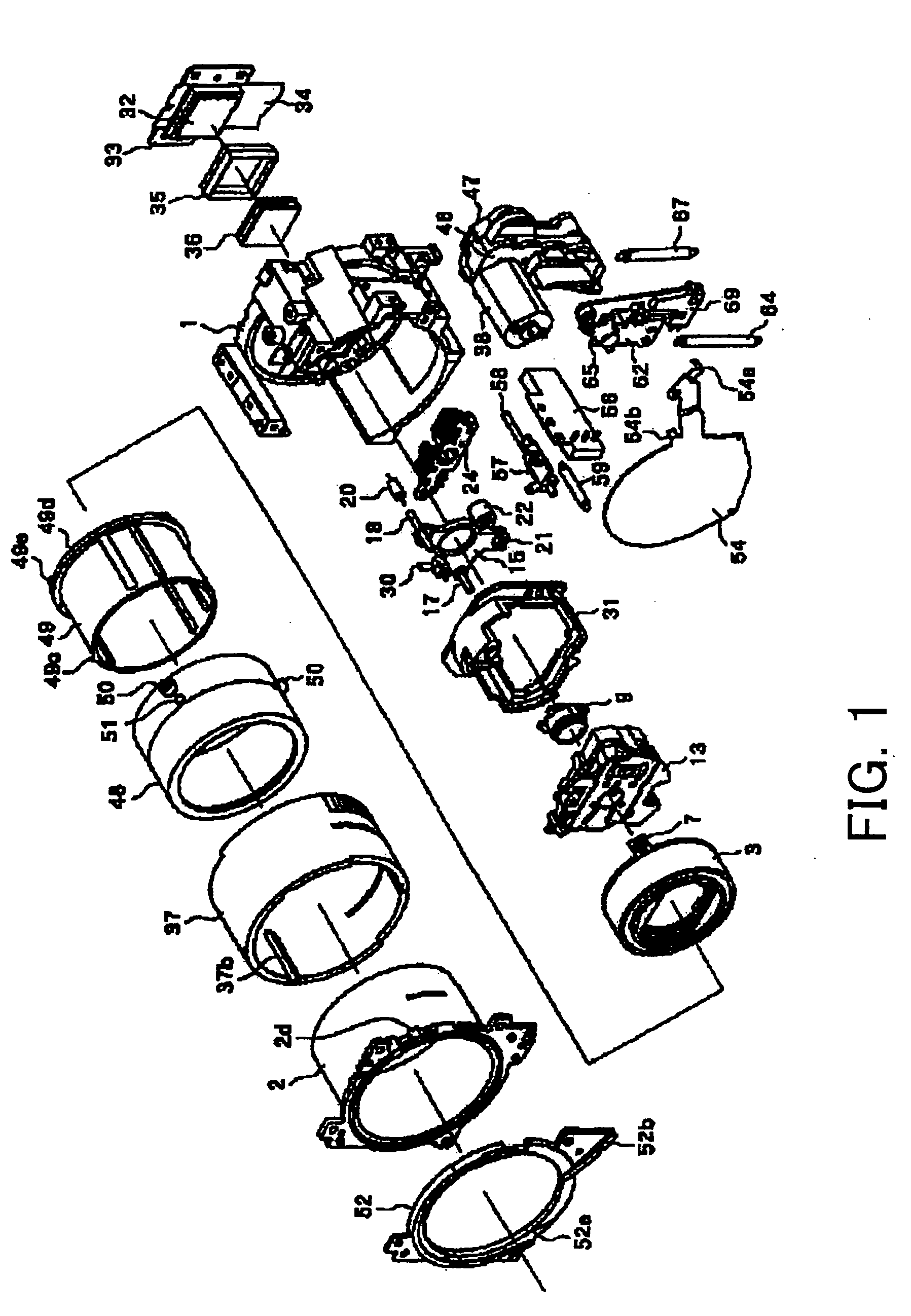
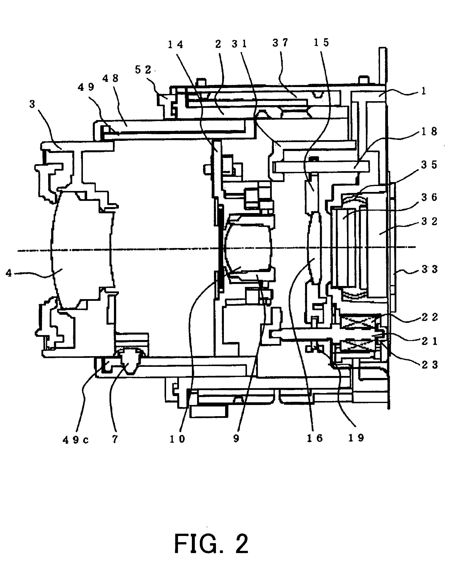
[0040]FIG. 1 is a perspective exploded view of a lens barrel portion of a digital camera (optical apparatus) that is Embodiment 1 of the present invention. FIG. 2 is a section view of the center of the lens barrel at the closest end (wide position). Embodiment 1 will hereinafter be described with reference to FIGS. 1 to 8.

[0041] Reference numeral 1 shows a base serving as a base portion of a lens barrel unit and forms the structure of the lens barrel unit together with a fixed barrel 2, which is fixed to the front end of the base 1 by screws. Reference numeral 3 shows a first lens barrel unit, which holds a first lens 4. Three follower pins 7 each having a taper portion at the end are pressed into the outer peripheral surface.

[0042] Reference numeral 9 shows a second lens barrel unit which holds a second lens 10 and is integrally held on an aperture base plate 14 of an aperture unit 13 by means of adhesion or the like.

[0043] Reference numeral 15 shows a third lens ba...

Example

Embodiment 2

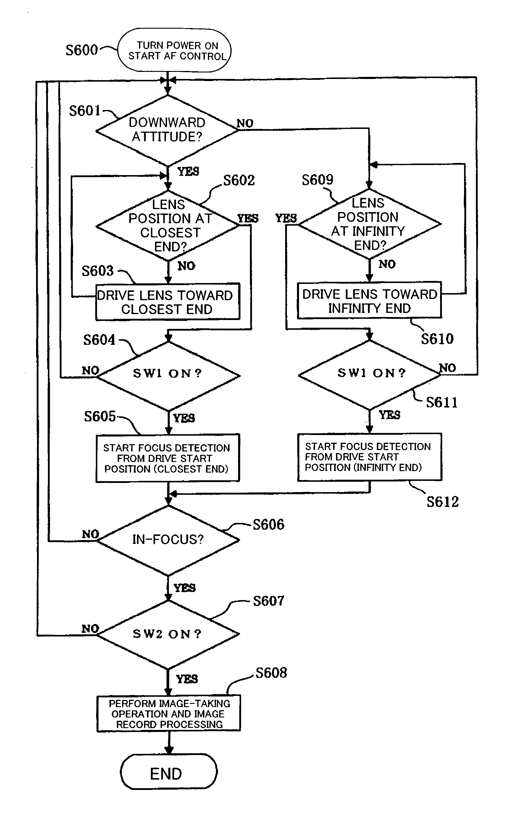
[0086] Embodiment 2 of the present invention will be described with reference to FIGS. 9 and 10. Embodiment 2 employs the “full range scan method” in the digital camera of Embodiment 1 described above, instead of the “climbing method,” to control (change) the drive range of the focus lens. FIG. 10 shows a flow chart of the operation of the digital camera in Embodiment 2. Since the other structures are identical to those in Embodiment 1, the description thereof will be omitted.

[0087] First, similarly to Embodiment 1, when the power switch of the digital camera is turned on, the attitude detector 71 detects the attitude of the digital camera and the image pick-up device 32 takes the image of a subject. Then, the drive control of the focus lens 16 is started (S700).

[0088] From step 701 to step 704 and from step 710 to step 712, operation similar to the processing from step 601 to step 604 and from step 608 to step 610 of Embodiment 1 described above is performed.

[0089] ...

Example

[0101] Embodiment 3 of the present invention will hereinafter be described with reference to FIGS. 11 and 12. Embodiment 3 employs a light characteristic detector in Embodiment 1. FIG. 11 shows the main system structure of a digital camera in Embodiment 2. FIG. 12 shows a flow chart of the operation in Embodiment 3. Since the other structures are identical to those in Embodiment 1, the description thereof will be omitted.

[0102] The light characteristic detector 72 is a detector for detecting the type of a light source (natural light, artificial light or the like). The light characteristic detector 72 determines the light source based on its color temperature or temporal change (flicker), for example.

[0103] The temporal change of the light source is explained as follows. A fluorescent lamp produces flicker at twice the frequency of a commercial power supply and provides a waveform similar to that resulting from half-wave rectification of the power supply, and the maximum of the lig...


PUM


Abstract

An optical apparatus according to the present invention enables a reduced drive distance in focusing operation of a focus lens to allow focus detection and focusing operation in a short time period. The optical apparatus has a detection unit which detects the attitude of the optical apparatus; and a controller which performs focus control for driving a focus lens included in an image-taking optical system based on a focus state of the image-taking optical system. The controller changes a drive start position of the focus lens in accordance with the attitude of the optical apparatus before the focus state of the image-taking optical system starts to be taken.

Description

FIELD OF THE INVENTION [0001] The present invention relates to focus control in an optical apparatus. BACKGROUND OF THE INVENTION [0002] Auto-focus control for digital cameras or video cameras employs a contrast method which sets, as an in-focus position, the position of a lens where the high-frequency component of a luminance signal provided by an image pick-up device such as a CCD sensor is at the maximum level. [0003] Known contrast methods include a “climbing method” wherein a lens is moved in a direction in which the high-frequency component of a luminance signal (hereinafter referred to as an in-focus evaluation value (sharpness)) provided by an image pick-up device increases and the position of the lens where the in-focus evaluation value is at the maximum is set to an in-focus position, and a “full range scan method” wherein in-focus evaluation values are stored while a lens is driven throughout the distance-measuring range and the position of the lens corresponding to the m...

Claims


Application Information

Patent Timeline
IPC IPC(8): G02B7/08G03B13/36G02B7/28G03B13/34H04N5/232H04N101/00
CPCG02B7/08H04N5/23212G03B13/36H04N23/673
Inventor UEHARA, TAKUMI
Owner CANON KK
Why Eureka
Try Eureka