

Centrifugal fan and casing thereof
a centrifugal fan and fan casing technology, applied in the direction of machines/engines, stators, liquid fuel engines, etc., can solve the problems of noise and discharge pressure loss, disturbance of airflow, and difficulty in diverting existing parts or the like, so as to prevent the loss of discharge pressure at the exhaust port, increase air velocity and air quantity, the effect of increasing the velocity
- Summary
- Abstract
- Description
- Claims
- Application Information
AI Technical Summary
Benefits of technology
Problems solved by technology
Method used
Image

Examples
first embodiment
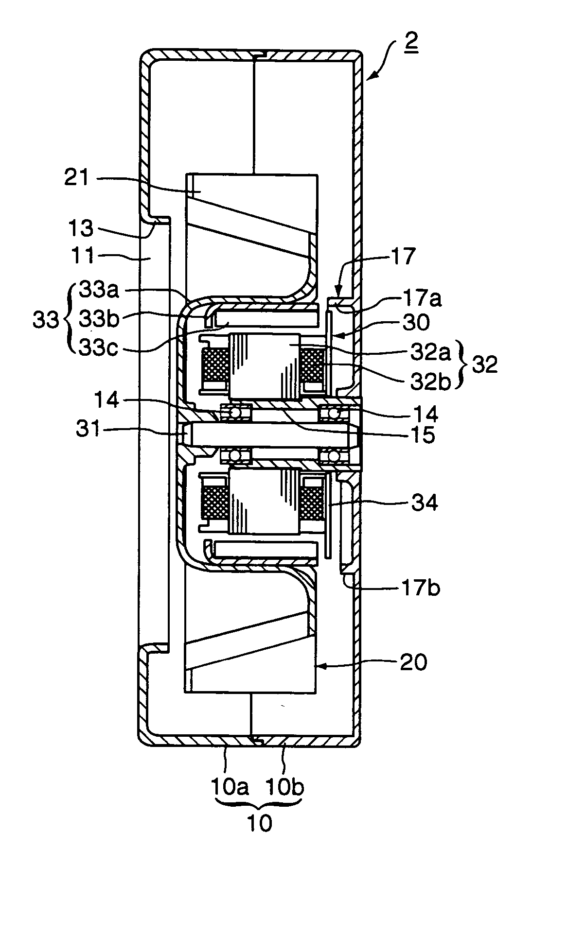
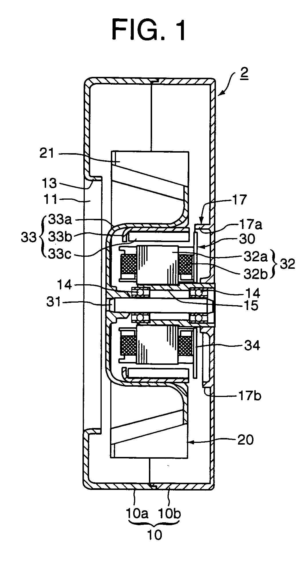
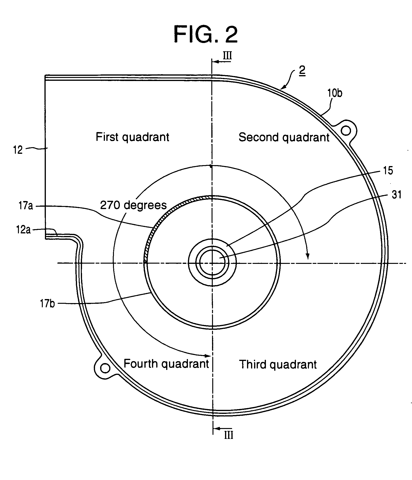
[0070]FIG. 1 is a sectional view showing a construction of a centrifugal fan according to a first embodiment of the present invention, FIG. 2 is a front view showing a second casing of the centrifugal fan shown in FIG. 1, and FIG. 3 is a sectional view of FIG. 2 along a III-III line. The first embodiment corresponds to the above-mentioned first aspect of the present invention.
[0071] A centrifugal fan 2 of the first embodiment is provided with a scroll casing 10 having an almost cylindrical shape in the same manner as the conventional example shown in FIG. 12 and FIG. 13. The resin made casing 10 consists of a first casing 10a and a second casing 10b. The first casing 10a constitutes one base wall and a part of a side circumferential wall of a cylinder, and the second casing 10b constitutes the other base wall and the remaining part of the side circumferential wall. An air inlet 11 that is opened in an axial direction is formed on a center portion of the base wall portion of the fir...
second embodiment
[0082]FIG. 4 is a sectional view showing a second casing of a centrifugal fan according to a second embodiment in the same manner as FIG. 3. The second embodiment corresponds to the above-mentioned first aspect of the present invention.
[0083] The entire configuration of a centrifugal fan of the second embodiment is the same as that of the first embodiment. In the second embodiment, the partition 17 is also formed on the inside of the base wall of the second casing 10b over the entire circumference. The partition 17 juts toward the impeller so as to close to the inner circumferential edge of the impeller. The partition 17 consists of the high partition 17a that has relatively large height in at least a region close to the exhaust port 12 and the low partition 17b that has relatively small height in the other region.
[0084] The connecting portion between the high partition 17a and the low partition 17b is formed as a vertical step shown by a dotted line in FIG. 4 in the second embodi...
third embodiment
[0085]FIG. 5 is a sectional view showing a construction of a centrifugal fan according to a third embodiment of the present invention. The third embodiment corresponds to the above-mentioned second and third aspects of the present invention.
[0086] A centrifugal fan 3 of the third embodiment is provided with a scroll casing 10A having an almost cylindrical shape in the same manner as the first embodiment. The resin made casing 10A consists of a first casing 10c and a second casing 10b. The first casing 10c constitutes one base wall and a part of a side circumferential wall of a cylinder, and the second casing 10b constitutes the other base wall and the remaining part of the side circumferential wall. An air inlet 11 that is opened in an axial direction is formed on a center portion of the base wall portion of the first casing 10c, and an exhaust port 12 that is opened in a circumferential direction is formed on one position of the side circumferential wall in the same manner as that...
PUM
 Abstract
Description
Claims
Application Information