
Exercising device

a technology of exercise device and articulating ring, which is applied in the field of exercise device, can solve the problems of unhealthful and dangerous consequences, affecting the exercise of other relatively unaffected body parts, and even presenting significant obstacles to exercising other relatively unaffected body parts, and unable to achieve the effect of exercising, and causing pain and pain in the joints and tendons,

Inactive Publication Date: 2005-09-22
KASSEL ARTHUR MICHAEL +1
View PDF14 Cites 6 Cited by
  • Summary
  • Abstract
  • Description
  • Claims
  • Application Information

AI Technical Summary

Benefits of technology

[0014] When using the device, rotation of the drive shaft causes repeated extension and retraction of a persons arms and legs, as well as rotation of the ankles, thereby imparting a wide range of motions similar to those that might be experienced while walking.

Problems solved by technology

Such individuals, who may have suffered a spinal injury, stroke, multiple sclerosis (MS), muscular dystrophy (MD), or other similar injury or disorder that impairs mobility (either temporarily or permanently), may also find that their impairments can even present significant obstacles to exercising other relatively unaffected body parts.
A failure to do so can have painful, even unhealthful and dangerous consequences.
For example, immobility tends to lead rapidly to stiffened and painful joints and tendons.
Long-term immobility also leads to an overall deterioration of the cardiovascular system.
While the benefit of such exercise is indisputable, it can require considerable time and effort of both the afflicted individual and the assistant (therapist or volunteer).
While beneficial in many ways, these devices often have their limitations.
While the exercising device disclosed in the '399 patent has proven effective, it does not afford motion of the feet comparable to that which would be achieved in walking.

Method used


Image

  • Exercising device
  • Exercising device
  • Exercising device

Examples


Embodiment Construction

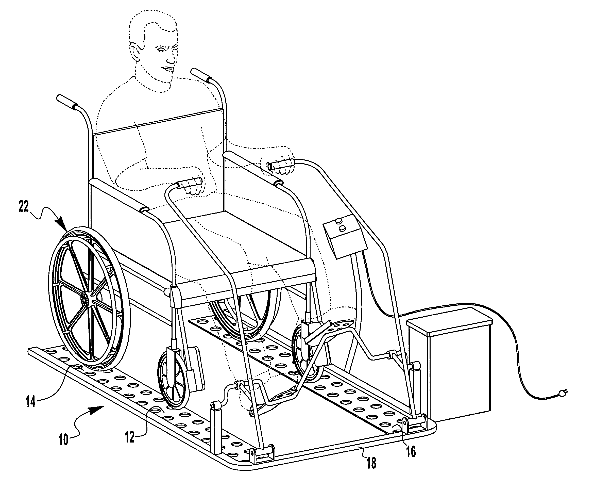
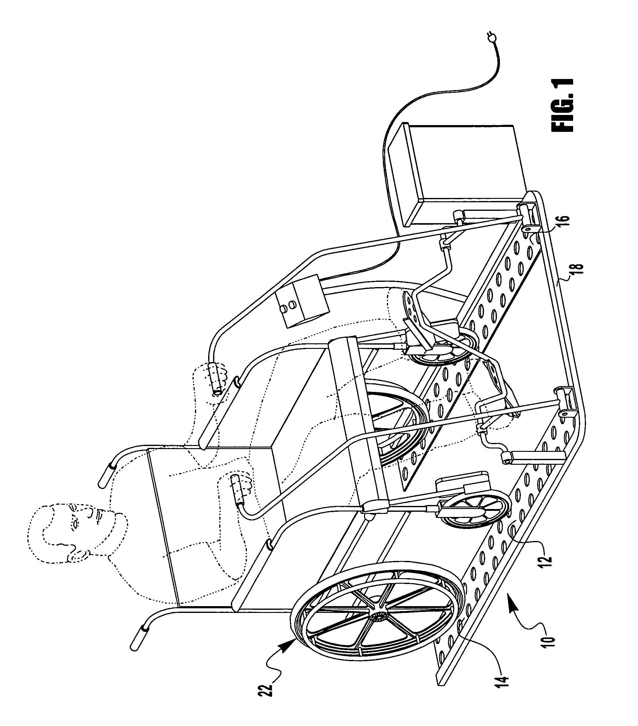
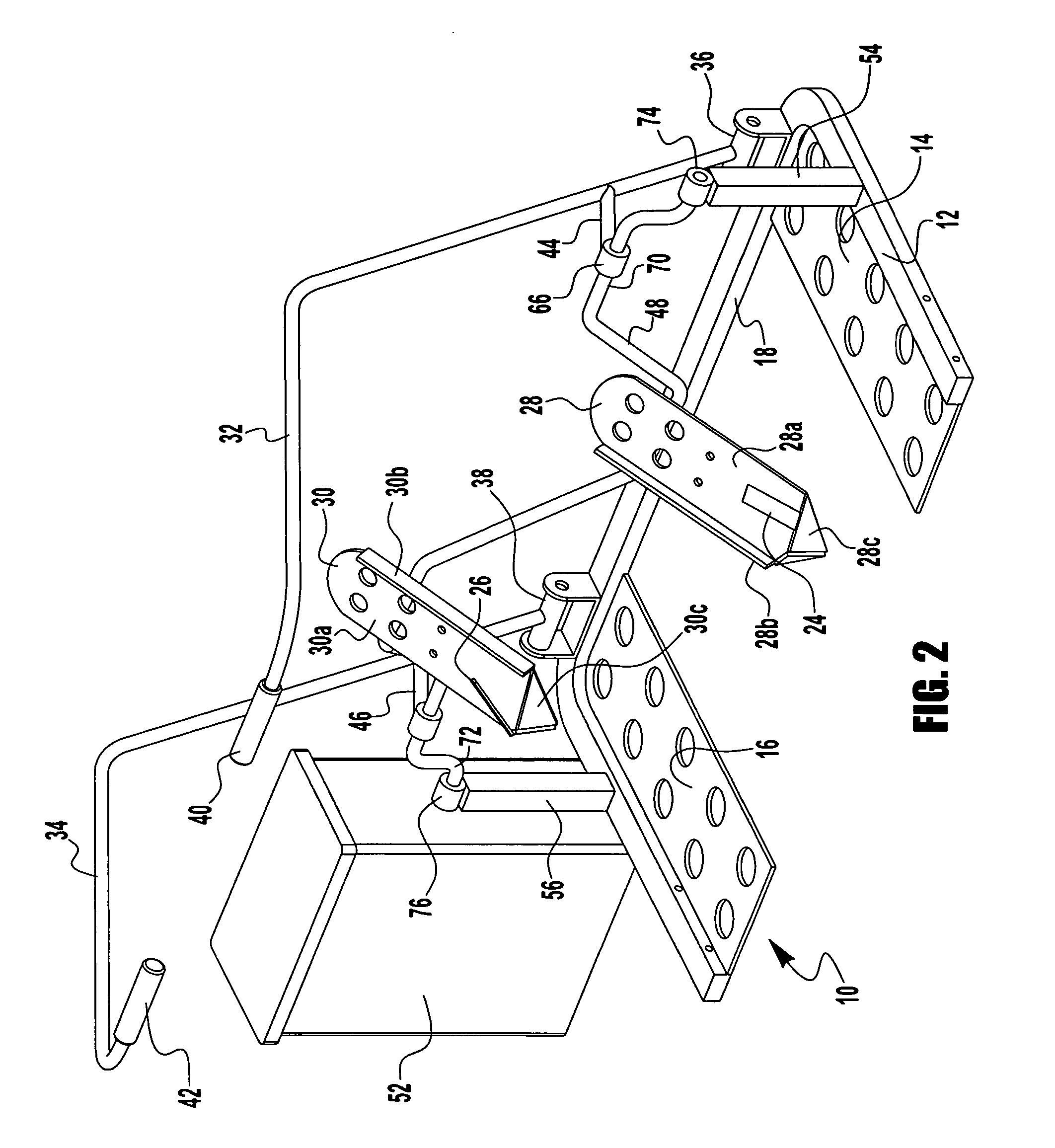
[0021] The exercising device 10, shown in FIGS. 1, 2 and 3, includes a frame 12, which is in turn made up of a pair of platforms 14, 16, and a rail 18. A wheelchair 22 rests on the platforms 14, 16 and may be positioned at any comfortable location and locked in place by a brake (not shown) on the wheelchair. The wheelchair 22 may be replaced by any type of chair, stool or bench. The patient sitting in the wheelchair can then be strapped by foot straps 24, 26 onto pedal plates 28, 30 in any desired manner to secure the shoes or feet of the patient onto the pedal plates 28, 30.

[0022] Arm exercising members 32, 34 are pivotally connected at pivot points 36, 38 to rail 18 and include a pair of handles 40, 42. Arm exercising members 32, 34 are caused to oscillate back and forth by movements transmitted via a pair of link arms 44, 46, which are connected between the arm exercising members and a shaft 48 that is rotated about an axis of rotation or centerline 50 by a motor drive device 52...


PUM


Abstract

An exercising device is described that permits exercising the arms and / or legs of a person, such as a wheelchair-bound person. The device has a drive shaft to which foot pedals are mounted. The foot pedals are mounted off of the axis of rotation and at an angle to the axis of rotation such that when a person's feet are strapped to the foot pedals and the drive shaft is rotated, the feet will circle the axis of rotation and will cause circular motion of the ankles. Arm exercising members are attached to the drive shaft will cause an oscillatory pivotal motion of the arm exercising members.

Description

CROSS-REFERENCE TO RELATED APPLICATIONS [0001] This application claims the benefit of U.S. Provisional Patent Application No. 60 / 425,181 filed on Nov. 8, 2003 which is incorporated herein by reference. [0002] This application is a continuation of copending PCT Patent Application No. PCT / US2003 / 35375 filed on Nov. 8, 2003, which is incorporated herein by reference.TECHNICAL FIELD OF THE INVENTION [0003] The present invention relates generally to exercising devices and more particularly to an exercising machine for use by a person that is not otherwise able to exercise their limbs by voluntary extension or contraction of their muscles. BACKGROUND [0004] It has long been known that for individuals who have limited mobility of their limbs, regular exercise can provide significant benefits. Such individuals, who may have suffered a spinal injury, stroke, multiple sclerosis (MS), muscular dystrophy (MD), or other similar injury or disorder that impairs mobility (either temporarily or perm...

Claims


Application Information

Patent Timeline
IPC IPC(8): A61H1/02A63B22/06A63B22/12A63B23/035A63B69/16A63B71/00
CPCA61H1/0214A61H1/0237A61H1/0274A63B21/00178A63B23/03575A61H2201/1671A63B2071/0018A61H1/0262A61H2201/1215A61H2201/1635A61H2201/164A63B71/0009
Inventor KASSEL, ARTHUR MICHAELRICHARDSON, KENNETH OWEN
Owner KASSEL ARTHUR MICHAEL
Learn More