Machine tool and method for operating a machine tool

a machine tool and machine tool technology, applied in the direction of metal-working holders, supporters, positioning apparatus, etc., can solve the problems of severe disruption of the production sequence, affecting the production sequence, and difficult to place the machine tool in the suitable starting state, so as to reduce the down time resulting from unplanned interruptions in the production sequen

Active Publication Date: 2005-09-22
STAMA MASCHFAB GMBH
View PDF9 Cites 16 Cited by
  • Summary
  • Abstract
  • Description
  • Claims
  • Application Information

AI Technical Summary

Benefits of technology

[0009] It is an object of the present invention to provide a method and a machine tool of the kind mentioned at the beginning which allow down times resulting from unplanned interruptions in the production sequence to be reduced.

Problems solved by technology

However, the production sequence, which is already very efficiently configured nowadays, is severely disrupted if, during the operation of the machine tool, unexpected / unplanned interruptions occur, such as a power failure, an emergency stop triggered automatically or by hand, erroneous operation in the form of an unintended manual intervention or an overload situation which, for example, is caused by a tool breakage.
Depending on the cause of the unplanned stop and depending on the current operating situation in which the interruption occurred, however, it is currently difficult to place a machine tool in the suitable starting state.
The stoppage times associated with this are detrimental to the production sequence.
In addition, there is the risk of a “crash” because of an erroneous operation in this situation.
However, this approach is restricted to situations in which the electric power supply fails unexpectedly.
However, in spite of such individual measures, there remains a whole series of scenarios in which a restart of the machine tool is complicated and lengthy, which can lead to long down times of the machine.

Method used


Image

  • Machine tool and method for operating a machine tool
  • Machine tool and method for operating a machine tool
  • Machine tool and method for operating a machine tool

Examples


Embodiment Construction

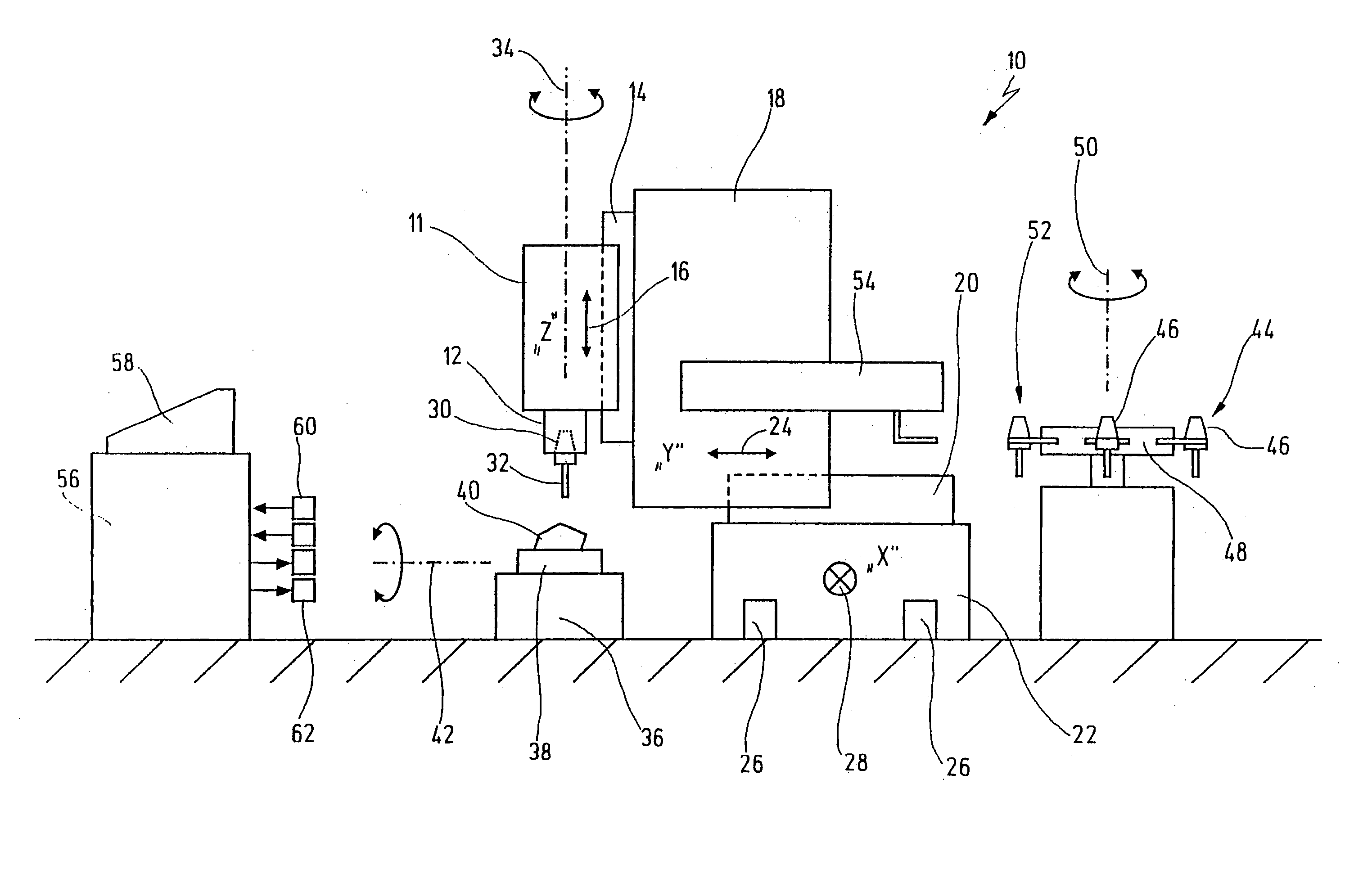
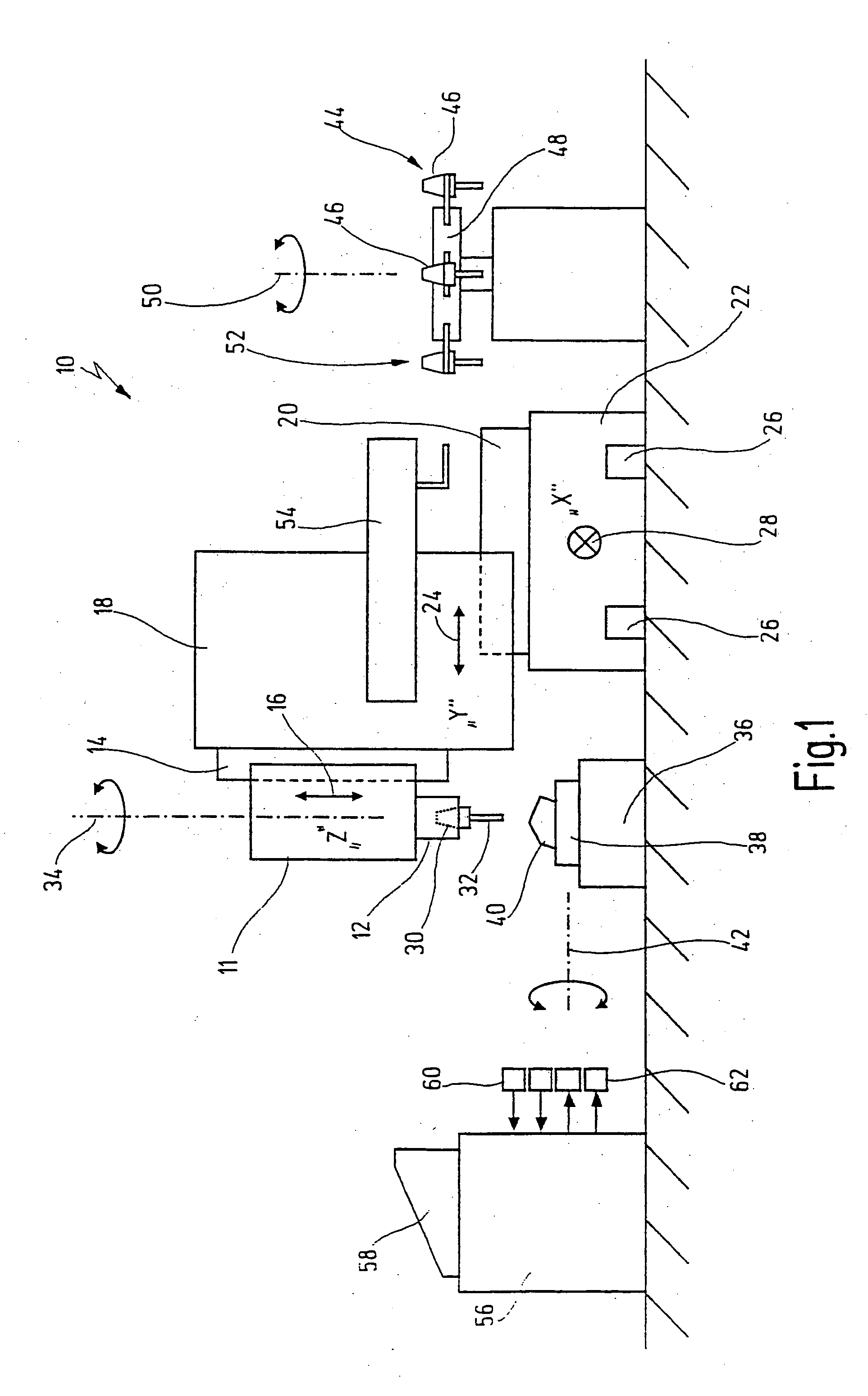
[0050] In FIG. 1, a machine tool in accordance with the invention is designated overall by the reference number 10.

[0051] The machine tool 10 has a spindle box 11 comprising an operating spindle 12, which represents a tool carrier in the sense of the present invention. Spindle box 11 is here arranged on a machine part 18 via a first guide carriage 14 such that it can move in the direction of an arrow 16. Movement in the direction of arrow 16 is usually designated a movement in the z direction.

[0052] Machine part 18 is mounted on a further machine part 22 via a second guide carriage 20 and can accordingly move in the direction of an arrow 24, i.e. in the y direction. Machine part 22 is in turn seated on guide rails 26, again such that it can move, the movement direction (x direction) perpendicular to the plane of the paper being indicated in the usual way by symbol 28. Overall, spindle box 11 including operating spindle 12 can therefore be moved in all three spatial directions and,...


PUM


Abstract

A machine tool comprises a tool carrier moveable relative to a workpiece to be machined. A controller controls the relative movement of the tool carrier and the workpiece by means of a control program. If an unplanned event occurs during the operational movement of the machine, the relative movement of the tool and the workpiece is stopped, and a restart from a starting position is carried out later. The starting position is in this case approached along a trajectory, and the trajectory is determined automatically as a function of the machining operation in which the unplanned event occurred.

Description

CROSS-REFERENCES TO RELATED APPLICATIONS [0001] This application is a continuation of copending international patent application PCT / EP2003 / 012321, filed on Nov. 5, 2003 designating the U.S. and published on Jun. 3, 2004 in German language, which international patent application claims priority under the Paris Convention from German patent application 102 55 033.6 filed on Nov. 19, 2002. These prior applications are incorporated by reference herein.BACKGROUND OF THE INVENTION [0002] The present invention relates to a method for operating a machine tool and to a machine tool operated in accordance with this method. More particularly, the invention relates to a method of controlling relative movements of a tool held in the machine and a workpiece after an unexpected or otherwise unplanned interruption of the machining operation occurred. [0003] Modern machine tools for metal cutting machining of workpieces are capable of carrying out a large number of complex machining operations in a...

Claims


Application Information

Patent Timeline
Patent Type & Authority Applications(United States)
IPC IPC(8): G05B19/4067G06F19/00
CPCG05B19/4067G05B2219/50108Y10T483/10Y10T82/2541G05B2219/50111
Inventor GRUND, PETERKUPPINGER, ROLFFROMMER, KARL
Owner STAMA MASCHFAB GMBH
Why Eureka
Try Eureka