Indirect evaporative cooling of a gas using common product and working gas in a partial counterflow configuration

a technology of working gas and common product, which is applied in the field of indirect evaporative coolers, can solve the problems of high cost of desiccant-dried air use, and achieve the effects of increasing the temperature of the working gas, increasing the latent heat load of the working air, and increasing the enthalpy of the exhaust air

Inactive Publication Date: 2005-09-29
IDALEX TECH INC
View PDF13 Cites 56 Cited by
  • Summary
  • Abstract
  • Description
  • Claims
  • Application Information

AI Technical Summary

Benefits of technology

[0021] Counter flow increases the temperature of the working gas by passing it in heat exchange first with the coldest product air then with warmer product air. A higher exhaust temperature will allow the air to hold much mo

Problems solved by technology

Thus, desiccant-dried air is expensiv

Method used


Image

  • Indirect evaporative cooling of a gas using common product and working gas in a partial counterflow configuration
  • Indirect evaporative cooling of a gas using common product and working gas in a partial counterflow configuration
  • Indirect evaporative cooling of a gas using common product and working gas in a partial counterflow configuration

Examples


Embodiment Construction

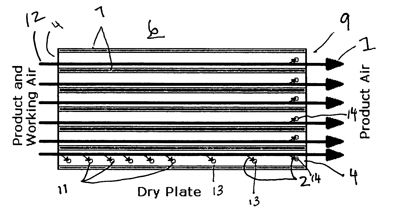
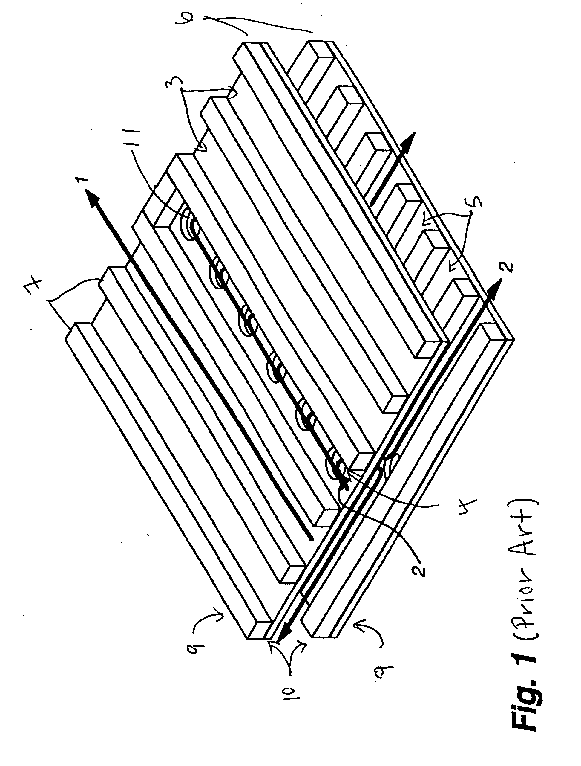
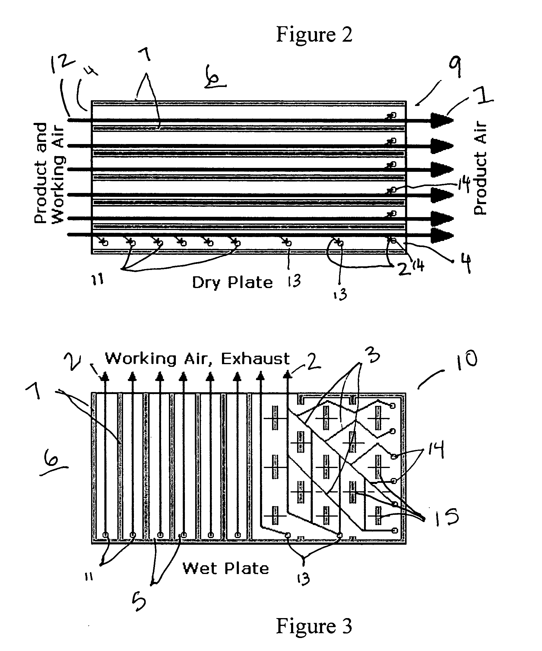
[0030]FIGS. 2-4 illustrate one embodiment of an indirect evaporative cooler wherein part of the product gas is used as working gas. Note that while the term “air” is frequently used in the following description, others types of gas may be used as well, so long as the same kind of gas is used for the product gas and the working gas. The following table lists reference numbers used in this patent:

1output product gas2output working gas3wet side paths4dry side channels5wet side channels6plates7channel guides8wick material9dry sides of plates10wet sides of plates11input end side perforations12Input common product and working air13output end side perforations14output end edge perforations15wet side path barriers

[0031]FIG. 2 is a plan view of the dry side 9 of a heat transfer plate 6 used in an evaporative cooler according to the present invention. Combined product and working air 12 enters dry side channels 4 from the left of the figure. Channels 4 are generally formed with a series of ...


PUM


Abstract

An indirect evaporative cooler includes a number of heat transfer plates. Each plate has a wet side and a dry side, and the dry sides of adjacent plates face each other. The plate dry sides have low permeability to an evaporative liquid. Input air flows over the dry sides from an input end to an output end. Part of the input air becomes product air and exits at the output end. The rest of the input air passes through perforations in the plates to the other side of the plates to become working air. The other side of each plate is a wet side, which is wet by an evaporative liquid. Working gas flows over the wet side, evaporating the evaporative liquid and cooling the evaporative liquid, the plate, and finally the product gas by heat transfer. The perforations are formed both toward the input end of the plate and toward the output end of the plate. Part of the wet side of the plate, toward the output end of the plate, has a plurality of barriers placed to cause the working gas at that end of the plate to flow in a direction generally counter to the input air.

Description

[0001] U.S. Pat. No. 6,581,402, issued Jun. 24, 2003 is incorporated herein by reference. U.S. Pat. No. 6,705,096, issued Mar. 16, 2004 is incorporated herein by reference. U.S. patent application Ser. No. 11 / 061,124, filed on Feb. 18, 2005, entitled “Plate Exchanger Edge Extension” is incorporated herein by reference. This application claims the benefit of U.S. Provisional Patent Application No. 60 / 553,875, filed Mar. 17, 2004BACKGROUND OF THE INVENTION [0002] 1. Field of the Invention [0003] The present invention relates to indirect evaporative coolers. In particular, the present invention relates to such coolers configured to utilize common product and working gas, with part of the working gas flowing in a counter-direction to the product gas. [0004] 2. Discussion of the Background Art [0005] Indirect evaporative cooling is a method of cooling a fluid stream; usually air, by evaporating a cooling liquid, usually water, into a second air stream while transferring heat from the fir...

Claims


Application Information

Patent Timeline
IPC IPC(8): F24F1/0059F24F5/00F25D17/06F28D5/00F28D5/02
CPCF24F5/0035F24F2001/0092Y02B30/545F28D5/02F28D5/00F24F1/0007Y02B30/54F24F1/0059
Inventor GILLAN, LELAND E.MAISOTSENKO, VALERIYGILAN, ALAN D.GILLAN, RICK J.
Owner IDALEX TECH INC
Why Eureka
Try Eureka