Capacitive acceleration sensor system

Inactive Publication Date: 2005-09-29
DENSO CORP
View PDF7 Cites 28 Cited by
  • Summary
  • Abstract
  • Description
  • Claims
  • Application Information

AI Technical Summary

Benefits of technology

[0014] In view of the above-described problem, it is an object of the present invention to provide a capacitive acc

Problems solved by technology

However, as sensor components are microminiaturized as mentioned above, problems become prone to occur.
Such problems include malfunctions due to breakage in a beam portion that couples an inertial displacement body with a frame, fine foreign particle bitten in between electrodes.
However, the technologies disclosed in the above prior arts have problems.
As a result, some drawbacks are caused.
As an example, it will be assumed that the displacement rigidity of a movable electrode becomes abnormal due to breakage, lodging of foreign particle, or the like.
Even when any anomaly occurs, therefore, it is difficult to find.
As a result, the zero point of a charge-voltage conversion circuit takes forever to stabilize, and thus a problem occu

Method used


Image

  • Capacitive acceleration sensor system
  • Capacitive acceleration sensor system
  • Capacitive acceleration sensor system

Examples


Example

[0029] (First Embodiment)

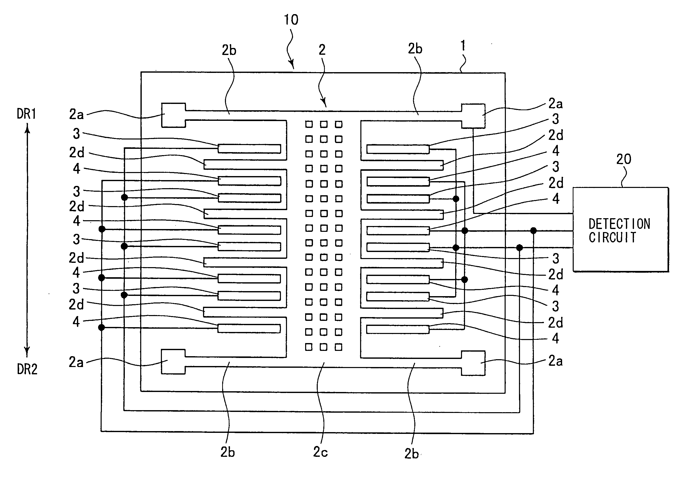
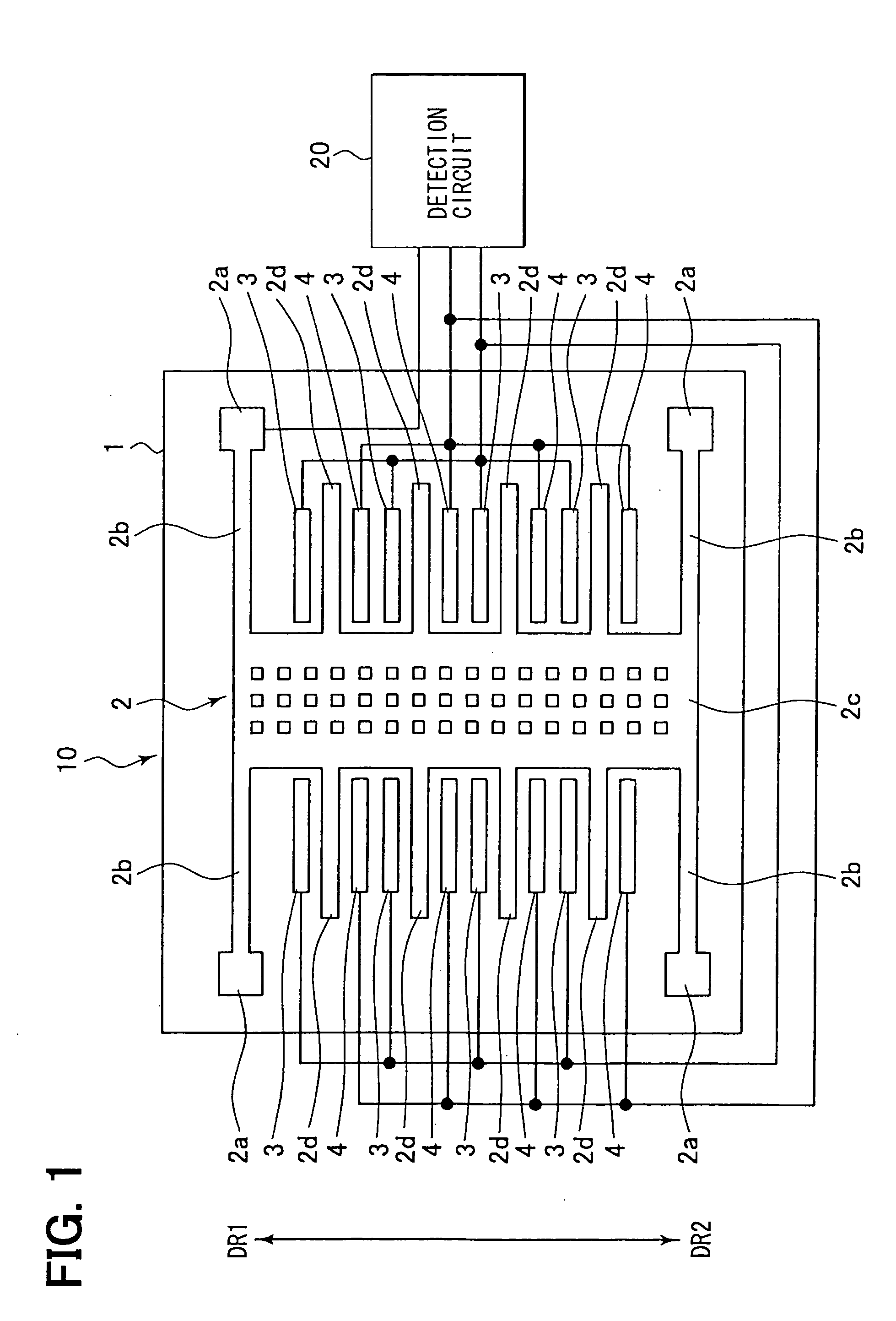
[0030]FIG. 1 illustrates an example of the constitution of a capacitive sensor unit for use in an acceleration sensor system according to a first embodiment of the present invention. The sensor unit comprises a sensor element 10 and a detection circuit 20. In the sensor element 10, an inertial displacement body 2c that senses acceleration and develops displacement is coupled with a substrate 1 by anchor portions 2a through beam portions 2b. The substrate 1 functions as a sensor frame. Movable electrodes 2d are integrated with the inertial displacement body 2c, and fixed electrodes 3 and 4 are formed on the substrate 1 so that they are opposed to the movable electrodes 2d. The inertial displacement body 2c, the beam portions 2d, the anchor portions 2d, and the movable electrodes 2d integrally provide a beam structure 2.

[0031] In this embodiment, the beam structure 2 is so formed that it is in plate shape as a whole. The inertial displacement body 2c is rect...

Example

[0064] (Second Embodiment)

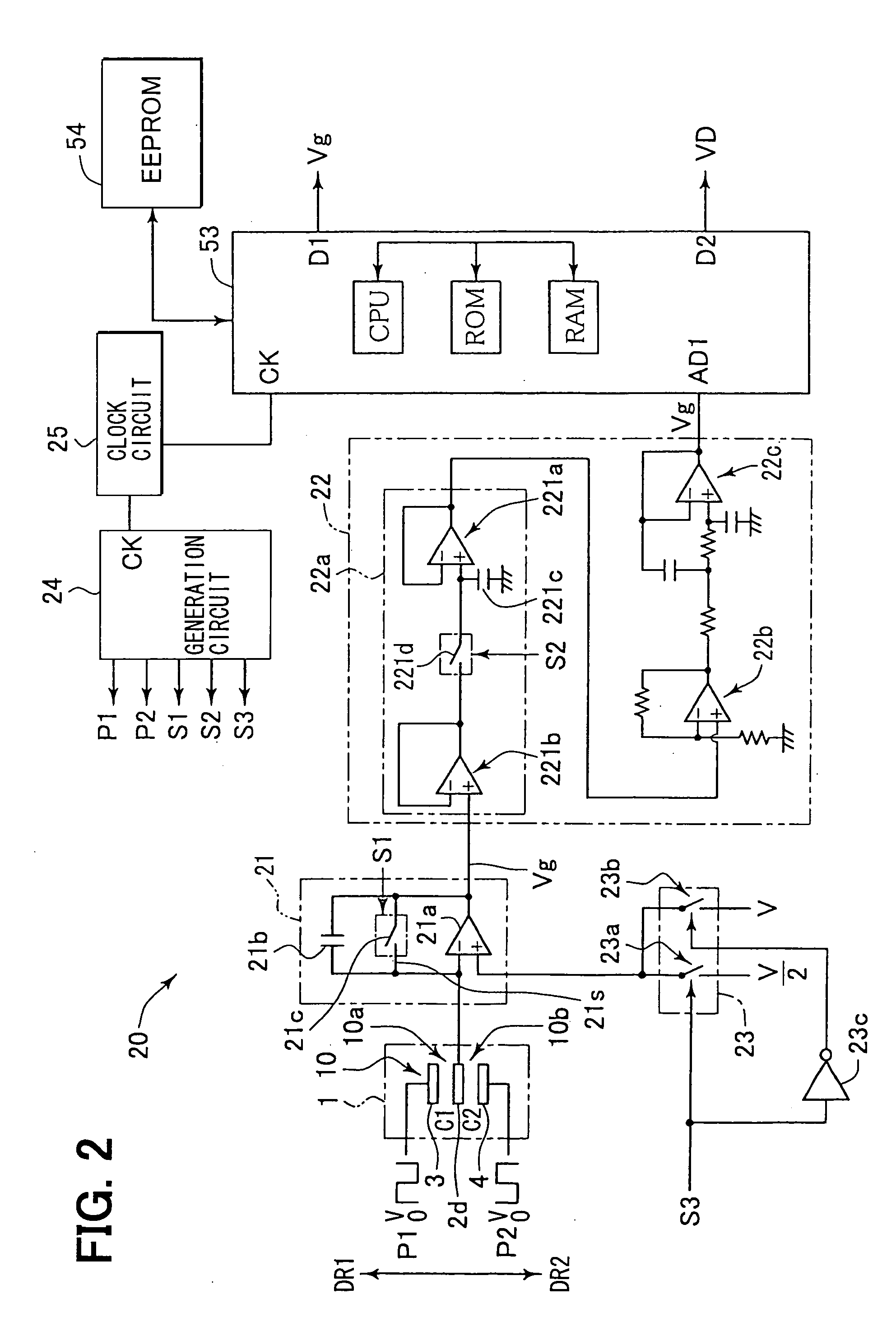
[0065] Another detection circuit 20 according to a second embodiment of the present invention is described with reference to FIG. 4. The detection circuit 20 includes as substantial parts the charge-voltage conversion circuit 21, the signal processing circuit 22, the control signal generation circuit 24, and the microcomputer 53. The charge-voltage conversion circuit 21 comprises the operational amplifier 21a provided with the negative feedback capacitor 21b for charge detection. Change in the charge output of the detection capacitors 10a and 10b is inverted and inputted. The charge-voltage conversion circuit 21 thereby converts it into voltage and outputs it as an acceleration signal. The inverting input terminal of the operational amplifier 21a is connected to the movable electrodes 2d. When V is taken as bias voltage for detection to the detection capacitors 10a and 10b, a voltage of V / 2 is inputted to the non-inverting input terminal of the operational...


PUM


Abstract

An acceleration sensor system includes: a first and a second fixed electrodes; a movable electrode for providing a first and a second capacitors; a detection capacitor for detecting a capacitance difference between the first and the second capacitors; a charge voltage conversion circuit for converting a capacitance change of the detection capacitor to an output voltage; a detection bias voltage applying means; a vibrating means for vibrating the movable electrode such that a displacement bias voltage is applied in a first period and no displacement bias voltage is applied in a second period; a sampling means for sampling the output voltage during the second period when the movable electrode is stationarily vibrated; and an acceleration signal generating and outputting means for generating an acceleration signal on the basis of a sampling result.

Description

CROSS REFERENCE TO RELATED APPLICATIONS [0001] This application is based on Japanese Patent Applications No. 2004-90409 filed on Mar. 25, 2004, and No. 2004-136418 filed on Apr. 30, 2004, the disclosures of which are incorporated herein by reference. FIELD OF THE INVENTION [0002] The present invention relates to a capacitive acceleration sensor system suitably used for an automotive vehicle control. BACKGROUND OF THE INVENTION [0003] As disclosed in Japanese Unexamined Patent Application Publication No. H6-74968 and Japanese Unexamined Patent Application Publication No. 2000-81449 (which corresponds to U.S. Pat. No. 6,257,061), capacitive acceleration sensors are in wide use in vehicle control and the like. This type of acceleration sensor has a capacitor for detection in which the distance between electrode plates is variable. The acceleration sensor is so designed that the following operation is performed: the state of charge storage in the capacitor based on change in the distanc...

Claims


Application Information

Patent Timeline
IPC IPC(8): G01P15/125
CPCG01P15/125
Inventor UMEMURA, AKINOBUITO, HIROKAZU
Owner DENSO CORP
Why Eureka
Try Eureka