Variable valve timing control device of internal combustion engine

Active Publication Date: 2005-09-29
DENSO CORP
View PDF7 Cites 69 Cited by
  • Summary
  • Abstract
  • Description
  • Claims
  • Application Information

AI Technical Summary

Problems solved by technology

However, in a hydraulically driven variable valve timing device like this there is the shortcoming that in cold conditions and on starting of the engine the hydraulic pressure is insufficient, the responsiveness of hydraulic control falls, and the accuracy of valve timing control falls.
However, in this motor-driven variable valve timing device of related art, because the construction is such that the motor as a whole rotates integrally with a pulley rotationally driven by the crankshaft, there is the shortcoming

Method used


Image

  • Variable valve timing control device of internal combustion engine
  • Variable valve timing control device of internal combustion engine
  • Variable valve timing control device of internal combustion engine

Examples


seventh embodiment

(Seventh Embodiment)

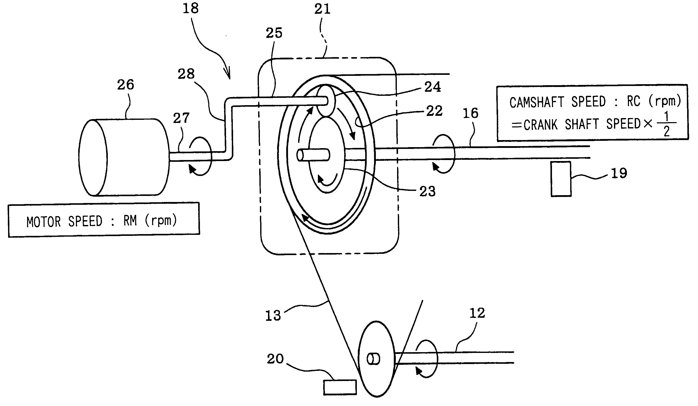
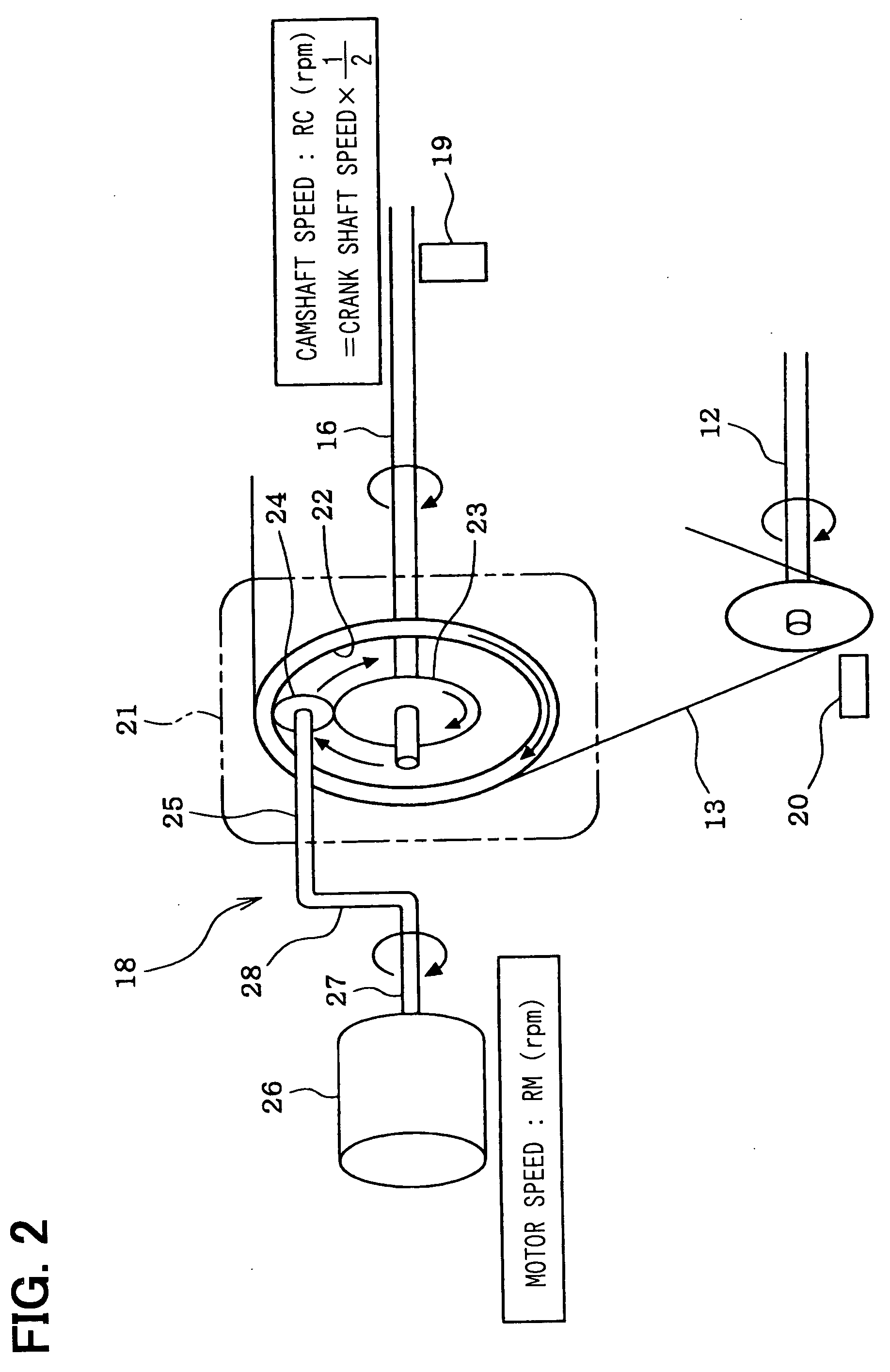
[0174] Next, a seventh embodiment will be described. In the sixth embodiment described above, a valve timing variation ΔVT was calculated on the basis of the motor speed RM of the motor 26 and the camshaft speed RC of the intake-side camshaft 16, and a final actual valve timing VT was obtained by adding to the actual valve timing VTC at the time of outputting of a cam angle signal the valve timing variation ΔVT subsequent to that.

[0175] With respect to this, in a seventh embodiment, the difference between the motor speed RM of the motor 26 and the camshaft speed RC of the intake-side camshaft 16 (the valve timing variation ΔVT) is calculated on the basis of a variation in the rotation angle of the motor 26 and a variation in the rotation angle of the camshaft, and a final valve timing is obtained by adding to the actual valve timing VTC at the time of outputting of a cam angle signal the valve timing variation ΔVT subsequent to that.

[0176] The seventh embodimen...

eighth embodiment

(Eighth Embodiment)

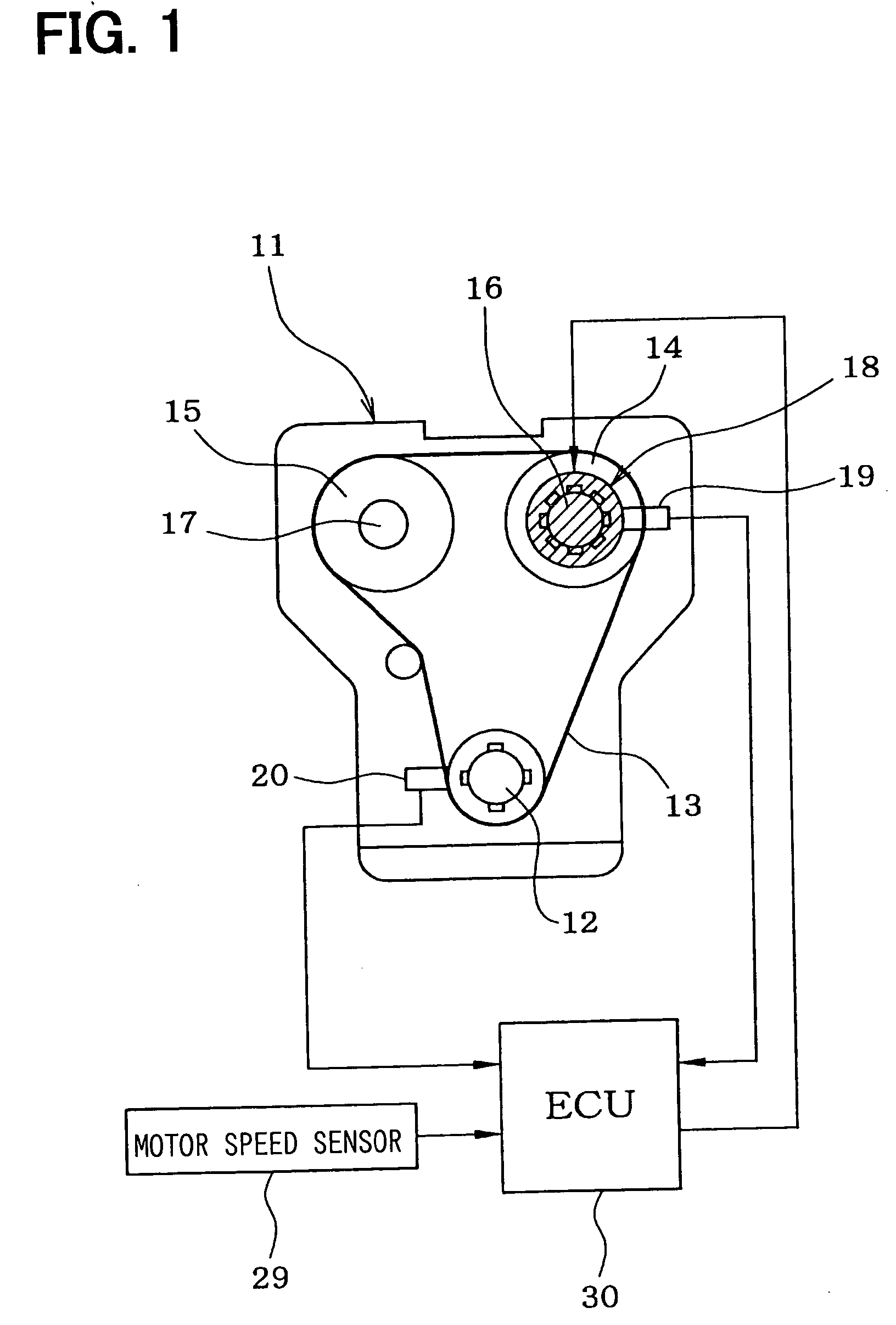
[0202] Next, an eighth embodiment of the invention will be described.

[0203] Generally, in a variable valve timing device, a limit position of the range of variation of the valve timing (a variable valve timing variation range limit position) is mechanically enforced by a moving part of the phase-varying mechanism being made to abut with a stopper part. Because of this, when the valve timing is controlled to a variation range limit position of a variable valve timing device (a most retarded angle position or a most advanced angle position) or to the proximity thereof, it sometimes happens that it overshoots and the moving part of the phase-varying mechanism is not sufficiently slowed and strikes the stopper part. And due to the impact load at the time of this impact a large load acts on the meshing parts of the gears of the phase-varying mechanism, there is a risk of the gears grinding and becoming locked and of the gear mechanism suffering damage, and there is a ...

ninth embodiment

(Ninth Embodiment)

[0228] Next, a ninth embodiment of the invention will be described, using FIG. 25 and FIG. 26.

[0229] The ECU 30, as described in the sixth embodiment, maintains the detection accuracy of the actual valve timing VT by learning a reference position of the valve timing (for example a most retarded angle position) every time predetermined learning conditions arise (for example every time a cam angle signal is inputted, or every time the engine is started). Therefore, when reference position learning has not been completed, because the detection accuracy of the actual valve timing VT has fallen (the detection error has increased), if the valve timing is controlled to or near to a limit position of its variation range in this state, there is a possibility of the moving part of the phase-varying mechanism 21 hitting a stopper part at high speed.

[0230] To avoid this, in this embodiment, the ECU 30, by executing a valve timing change rate limit control program shown in FI...


PUM


Abstract

A required valve timing change rate Vreq is calculated so as to make a deviation D between a target valve timing VTtg and an actual valve timing VT small and then a required speed difference DMCRreq between a motor 26 and a camshaft 16 is calculated on a basis of the required valve timing change rate Vreq. When the deviation D is larger than a predetermined value, a required motor speed Rmreq is calculated by adding the required speed difference DMCRreq to a camshaft speed RC and a motor control value is calculated so as to control the motor speed RM to the required motor speed Rmreq. When the deviation D is not larger than the predetermined value, the camshaft speed RC is set as the required motor speed Rmreq and the motor control value is calculated so as to control the motor speed RM to the camshaft speed RC.

Description

TECHNICAL FIELD [0001] This invention relates to a variable valve timing control device of an internal combustion engine, for varying the valve timing of intake valves or exhaust valves of an internal combustion engine. BACKGROUND ART [0002] In recent years, among internal combustion engines mounted in automotive vehicles, an increasing number have employed variable valve timing devices for varying the valve timing of intake valves and exhaust valves with the object of increasing output, reducing fuel consumption, and lowering exhaust emissions. Most variable valve timing devices in use at present change the valve timing of intake valves and / or exhaust valves driven to open and close by a camshaft by driving a phase-varying mechanism with hydraulic pressure to vary the rotation phase of the camshaft with respect to a crankshaft. However, in a hydraulically driven variable valve timing device like this there is the shortcoming that in cold conditions and on starting of the engine the...

Claims


Application Information

Patent Timeline
IPC IPC(8): F01L1/34F01L1/352F02D13/02
CPCF01L1/024F01L1/34F01L1/352Y02T10/18F01L2800/00F02D13/0238F02D13/0249F01L13/02Y02T10/12F02D13/02
Inventor URUSHIHATA, HARUYUKIIIDA, HISASHI
Owner DENSO CORP
Why Eureka
Try Eureka