Method and device for producing optical part

a technology of optical components and production methods, applied in the direction of dough shaping, manufacturing tools, instruments, etc., can solve the problems of uneconomical known methods, unable to meet the needs of customers, and the portion of molded products left unusable, so as to achieve smooth distribution, reduce production costs, and reduce the effect of air bubble generation

Inactive Publication Date: 2005-09-29
HOYA CORP
View PDF11 Cites 22 Cited by
  • Summary
  • Abstract
  • Description
  • Claims
  • Application Information

AI Technical Summary

Benefits of technology

[0042] With such an arrangement, since the raw material resin (preform) for a spectacle plus-power lens shows a profile that internally contacts the mold, i.e. the raw material resin contacts the molding surfaces of the mold at a central part thereof (e.g. double convex profile), the raw material resin is smoothly distributed during the pressurizing/molding process, so that profile a...

Problems solved by technology

However, the known injection molding methods are accompanied by drawbacks.
For example, raw material resin is also filled in the runner and the sprue in addition to the lens molding cavities (Document 1) and raw material resin can spill out from the mold (see FIGS. 6 and 8 of Document 2), so that raw material resin is required by a volume greater than the volume essentially necessary for the molded product, or the lens, to make the known methods uneconomic.
In other words, the r...

Method used


Image

  • Method and device for producing optical part
  • Method and device for producing optical part
  • Method and device for producing optical part

Examples


first embodiment

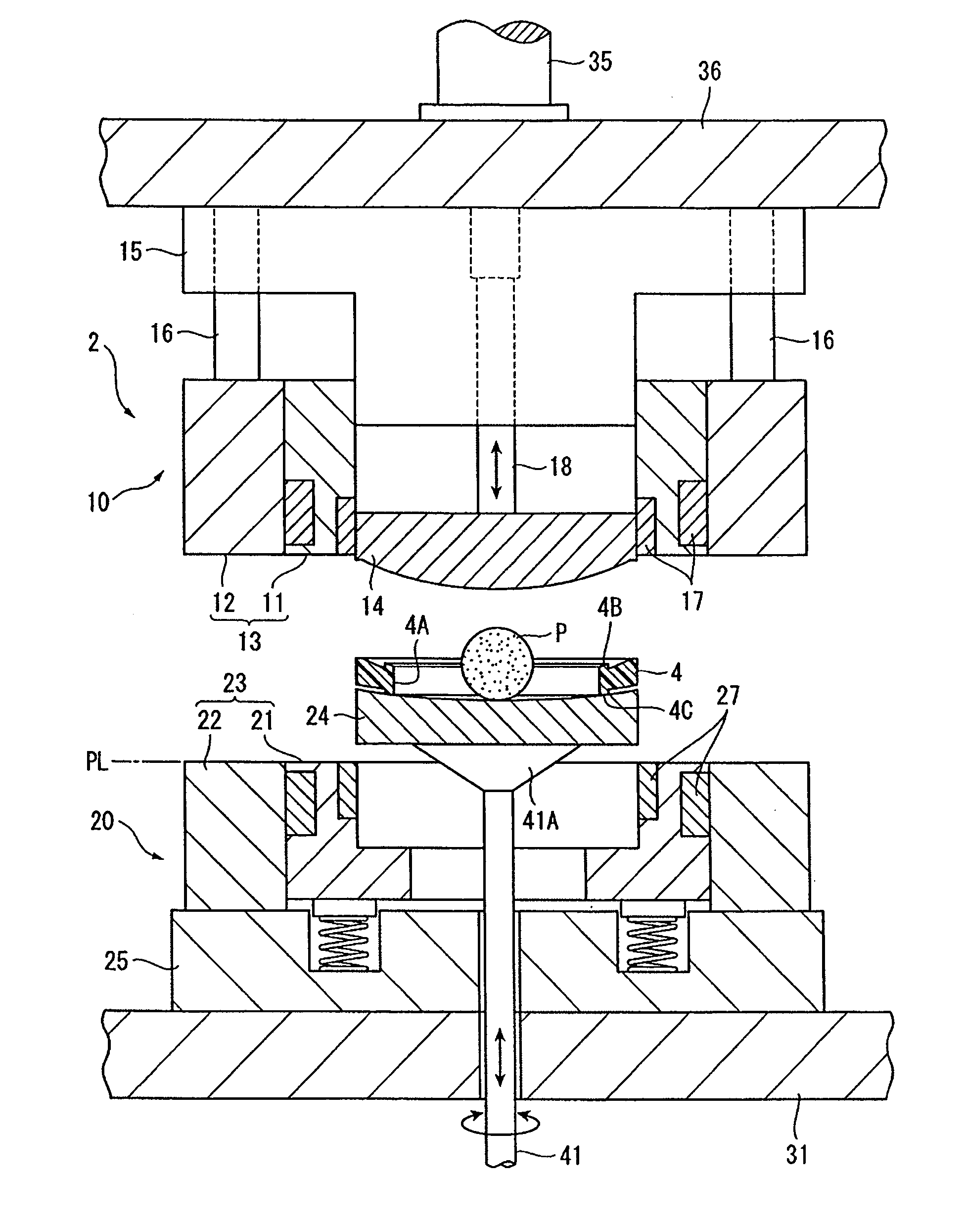
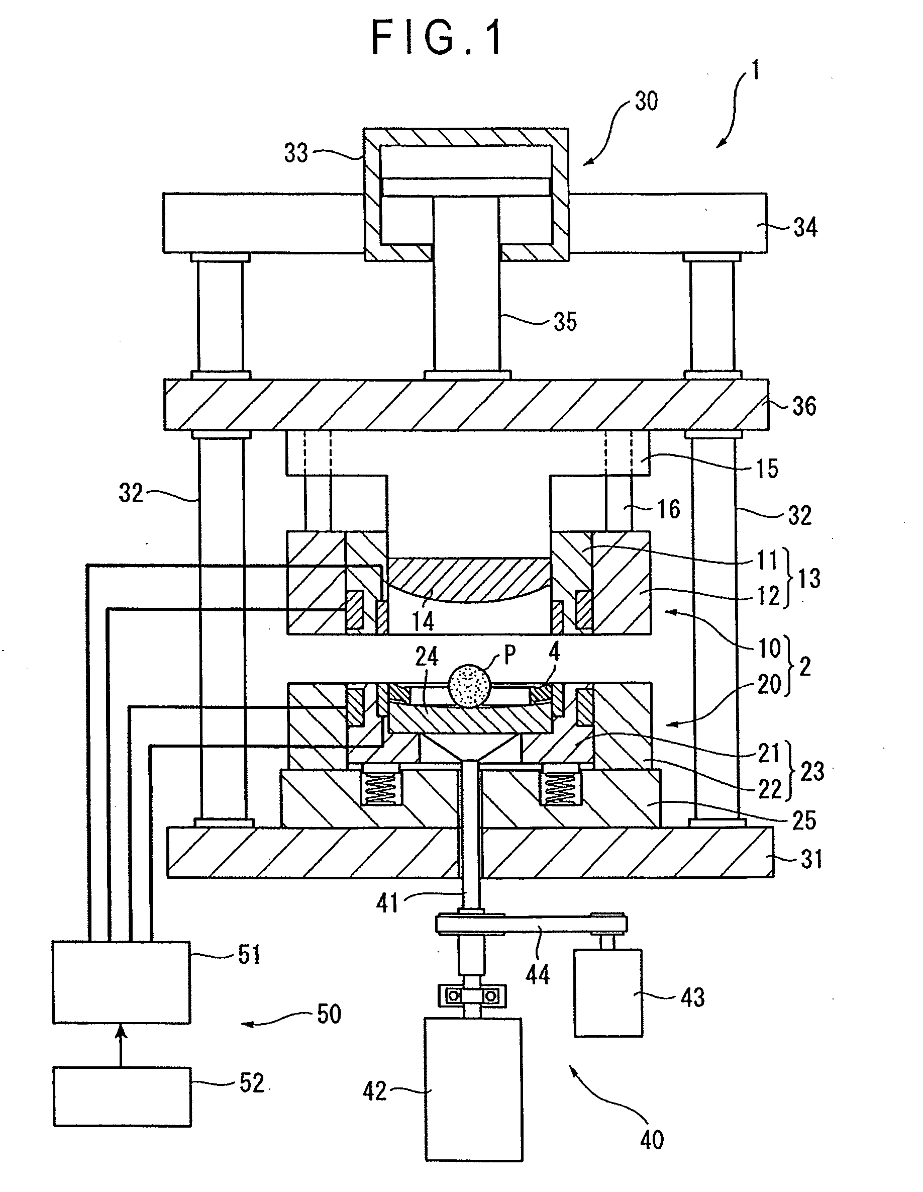
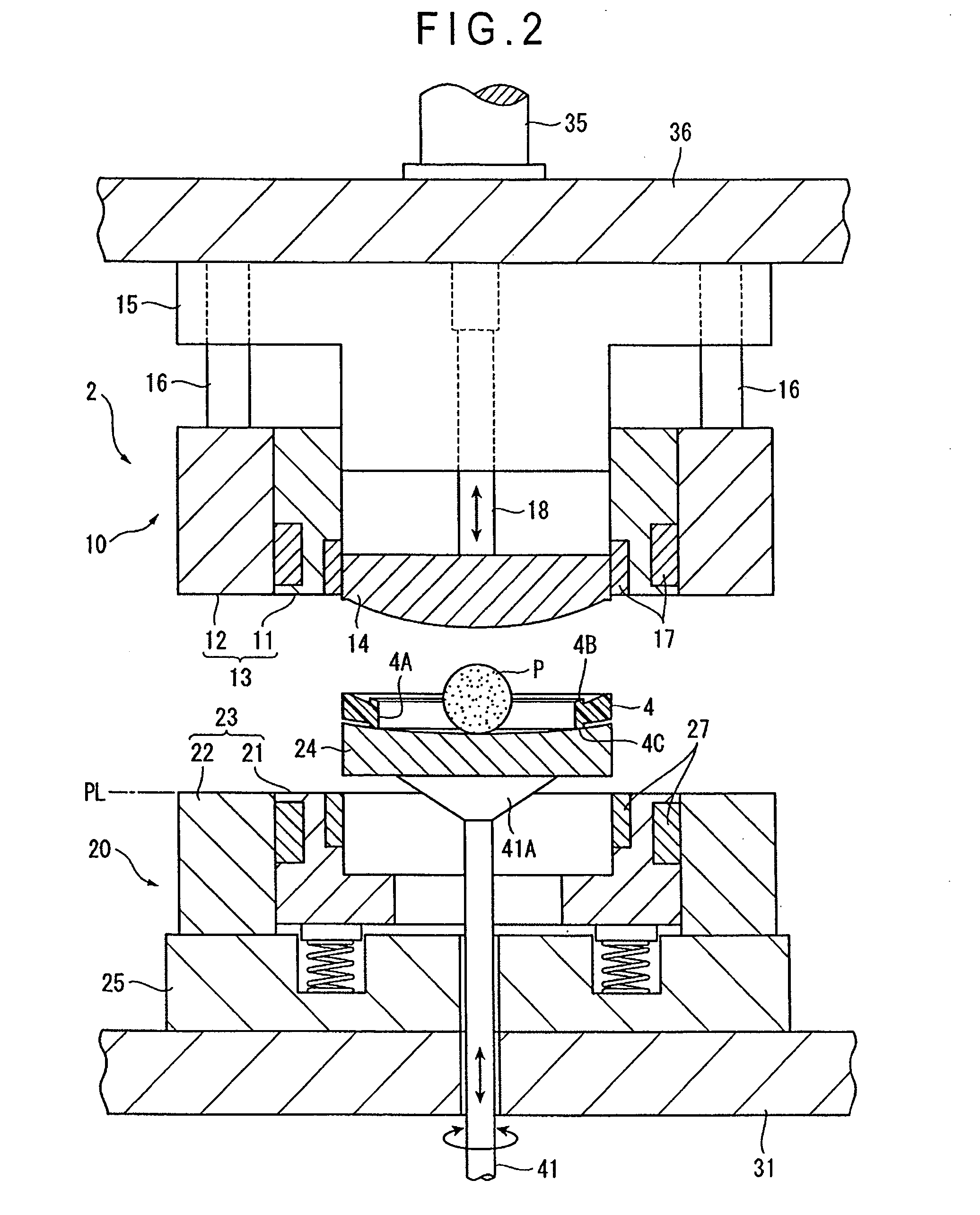
[0056]FIG. 1 is a schematic illustration of a device 1 for producing an optical component to which a method of producing an optical component according to a first embodiment of the present invention is applied, showing the. The optical component molded here is a minus spectacle lens (meniscus-shaped spectacle lens) whose thickness is greater at the central part than at the peripheral portion thereof.

[0057] The producing device 1 is a heating / pressurizing molding device that includes a mold clamping unit 30 containing a molding die 2, a positioning unit 40 for positioning the molding die 2 and a mold temperature regulating unit 50 for controlling the temperature of the molding die 2 at a predetermined temperature.

[0058] The mold clamping unit 30 includes a fixed die plate 31, a cylinder anchoring plate 34 rigidly secured to the fixed die plate 31 by way of a plurality of tie bars 32 and carrying a mold clamping cylinder 33 and a movable die plate 36 arranged so as to be elevatable ...

second embodiment

[0112]FIG. 9 is an illustration schematically showing an arrangement of a device for producing an optical component according to the present embodiment. Like the first embodiment, the producing device according to the second embodiment of the present invention is a heating / pressurizing molding device that includes a mold clamping unit 30 containing a molding die 2, a positioning unit 40 for positioning the molding die 2 and a mold temperature regulating unit 50 for controlling the temperature of the molding die 2 to a predetermined temperature. The producing device of this embodiment differs from the first embodiment in terms of the configuration of the upper mold insert (first mold) of the upper mold 10 of the molding die 2. Now, the difference will be described in detail below.

[0113] The upper mold insert 19 of this embodiment includes a glass mold 19A that is made of glass and has a molding surface, a spacer 19B arranged at a side of the glass mold 19A opposite to the molding su...


PUM

PropertyMeasurementUnit
Pressureaaaaaaaaaa
Elasticityaaaaaaaaaa
Hardnessaaaaaaaaaa

Abstract

An annular insert (4) is arranged in the optical component molding cavity of a mold to surround an outer periphery of raw material resin in a direction in which the resin is distributed in the cavity to limit the distribution of the raw material resin and define an outer profile of a lens (L). With this arrangement, it is only necessary to provide raw material resin only by a quantity equal to the volume of the region surrounded by the molding surfaces of upper and lower mold inserts (14, 24) and the inner peripheral edge of the annular insert (4) of the mold, so that the required volume of the raw material resin can be reduced. Since the pressure is preserved at the outer periphery of the distributed resin by the presence of the annular insert (4), the residual strain of the resin is minimized to prevent generation of sink mark, thereby providing excellent optical characteristics on the lens (L).

Description

BACKGROUND OF THE INVENTION [0001] 1. Field of the Invention [0002] The present invention relates to a method and a device for producing an optical component and also to an optical component. More particularly, the present invention relates to a method and a device for molding an optical component to be used as a lens for spectacles or an optical appliance by pressurizing and distributing a plasticized raw material resin contained in a mold cavity, and also to an optical component produced by the producing method and producing device. [0003] 2. Description of Related Art [0004] Methods for molding a resin optical component typically by means of injection compression molding are known (refer to, for example, Document 1: Japanese Patent Publication No. 3260072, and Document 2: International Publication WO99 / 24243 Leaflet). [0005] The injection compression molding method of Document 1 is designed so that a molten raw material resin is injected into and filled in a mold body having a pa...

Claims


Application Information

Patent Timeline
IPC IPC(8): B29C43/36B29D11/00
CPCB29C43/361B29C2043/3628Y10S425/808B29D11/00528B29L2011/0016B29D11/00413
Inventor INOUE, KAZUOSAITO, KIYOHIROUEHARA, TADAYOSHI
Owner HOYA CORP
Why Eureka
Try Eureka