Variable-reluctance resolver and rotational angle sensor using same

a technology of resistor and resolver, which is applied in the direction of electrical/magnetically converting sensor output, process and machine control, etc., can solve the problems of large output signal voltage error, large deviation of center deviation, and large deviation of accuracy of resolver. , to achieve the effect of reducing the influence of center deviation

Inactive Publication Date: 2005-09-29
MINEBEA CO LTD
View PDF32 Cites 8 Cited by
  • Summary
  • Abstract
  • Description
  • Claims
  • Application Information

AI Technical Summary

Benefits of technology

[0019] In view of the above drawbacks in a conventional apparatus, an object of the present invention is to provide a resolver which reduces an influen...

Problems solved by technology

In the case where the stator and the rotor are assembled in a misaligned state; i.e., the center axis of the rotor is deviated from the center axis of the stator, output signal voltages, which vary with the rotational angle of the rotor, greatly deviate from the designed output signal voltages, whereby the accuracy of the resolver deteriorates considerably.
Accordingly, even a small center deviation between the stator and the rotor produces large errors in the output signal voltages.
This means that a small variation in input causes a large variation in output, so that output errors are easily generated.
Moreover, when...

Method used


Image

  • Variable-reluctance resolver and rotational angle sensor using same
  • Variable-reluctance resolver and rotational angle sensor using same
  • Variable-reluctance resolver and rotational angle sensor using same

Examples


embodiment 1

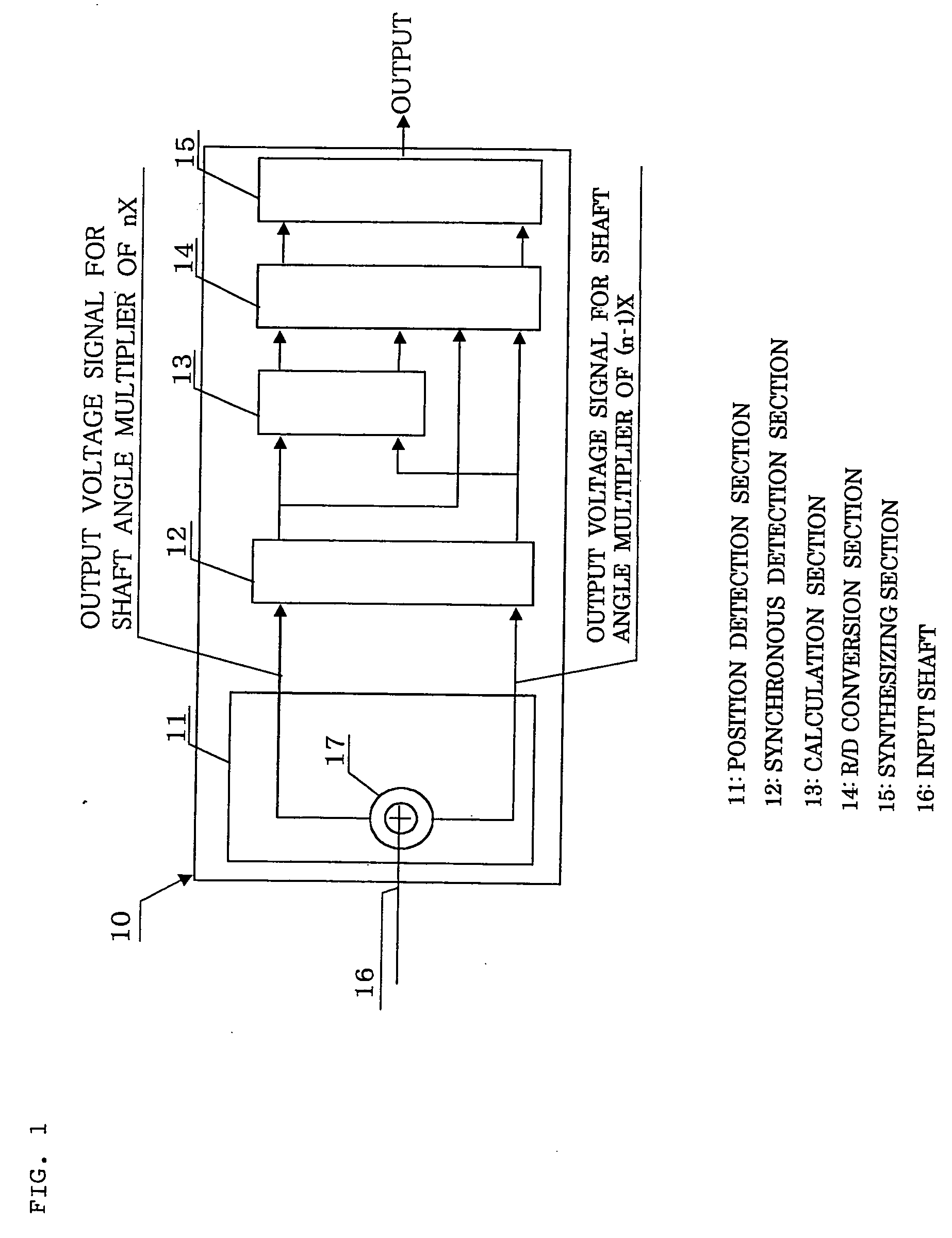
[0052]FIG. 1 is a block diagram of a rotational angle sensor according to the present invention. A rotational angle sensor 10 includes a position detection section 11, a synchronous detection section 12, a calculation section 13, a resolver-digital (R / D) conversion section 14, and a synthesizing section 15. The rotational angle sensor 10 has a housing for accommodating these sections, from the position detection section 11 to the synthesizing section 15. Although the housing preferably assumes a sealed structure, the housing may assume an open structure in which one end of the housing is opened for assembly with a casing of counterpart equipment to which an input shaft 16 is connected. The synchronous detection section 12, the calculation section 13, the resolver-digital (R / D) conversion section 14, and the synthesizing section 15 are mounted on a circuit board as needed. Further, these sections are integrated into an IC (integrated circuit) as needed. The circuit board which carrie...

second embodiment

[0077] Also, the calculation section 13 obtains the 1× resolver signal by obtaining Asinθ as described in the first embodiment, and further, performs the following calculation while using the output of the synchronous detection section 12 in the first embodiment. Asin⁢ ⁢3⁢ ⁢θ·A⁢ ⁢cos⁢ ⁢2⁢θ+ ⁢A⁢ ⁢cos⁢ ⁢3⁢θ·A⁢ ⁢sin⁢ ⁢2⁢θ⁢=A2⁢sin⁡(3⁢ ⁢θ+2⁢ ⁢θ)⁢=A2⁢sin⁢ ⁢5⁢ ⁢θ

Subsequently, the calculation section 13 converts the calculation result; i.e., A2sin5θ, to Asin5θ having the initial amplitude, and outputs Asin5θ. Thus can be obtained a resolver signal for the shaft angle multiplier of 5×; a continuous voltage signal whose period is 360 degrees (mechanical angle) and which consists of 5 triangular wave segments whose period is 360 / 5 degrees.

[0078] The R / D conversion section 14 receives the output voltage signal for the shaft angle multiplier of 1× and the output voltage signal for the shaft angle multiplier of 5× output from the calculation section 13 and, at each sampling time, converts them...

third embodiment

[0082]FIG. 4 is a view showing another example of the rotor of the present invention.

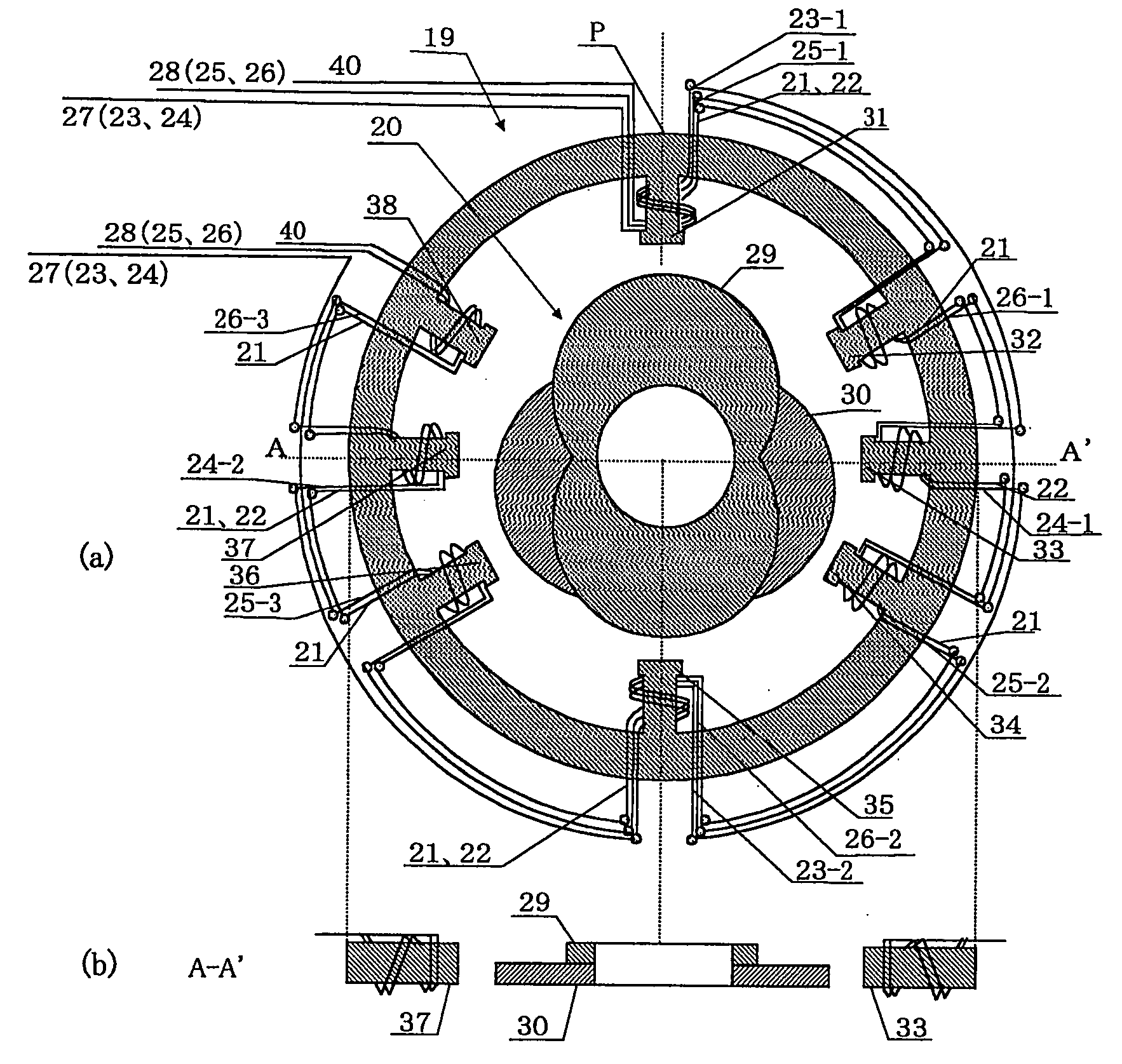
[0083] In the first embodiment shown in FIG. 3, the rotor is formed of a rotor portion having salient poles for the shaft angle multiplier of 2× and a rotor portion having salient poles for the shaft angle multiplier of 3×, which are superposed on each other. In the third embodiment, salient poles for the shaft angle multiplier of 2× and salient poles for the shaft angle multiplier of 3× are formed on a single annular plate such that the salient poles for the shaft angle multiplier of 2× are located on one side of a plane including the center axis, and the salient poles for the shaft angle multiplier of 3× are located on the other side of the plane. The salient poles for the shaft angle multiplier of 2× are formed in such a manner that a single complete salient pole is formed at the center and a half salient pole is formed on the left and right sides of the complete salient pole.

[0084] The numbers...


PUM


Abstract

A variable-reluctance resolver includes a rotor and a stator. The rotor includes axially connected first and second rotor portions. The first rotor portion has n salient poles provided about a center axis at uniform angular intervals, where n is an arbitrary integer not less than 3. The second rotor portion has (n-1) salient poles provided about the center axis at uniform angular intervals. The stator has a plurality of magnetic poles provided on an inner circumferential surface thereof. An excitation coil and output coils for shaft angle multipliers of n× and (n-1)× are provided on the magnetic poles in order to output sine and cosine outputs having a phase difference of 90 degrees therebetween. A rotational angle sensor includes the VR resolver and a calculation section for calculating a resolver signal for a shaft angle multiplier of 1× from signals output from the VR resolver.

Description

BACKGROUND OF THE INVENTION [0001] 1. Field of the Invention [0002] The present invention relates to a variable-reluctance (VR) resolver used for, for example, measurement or control of rotational angle or position, and to a rotational angle sensor using the same. [0003] 2. Description of the Related Art [0004] A variable-reluctance (VR) resolver, which includes a stator having an excitation winding and output coils wound around its magnetic poles, and a rotor having an arbitrary salient pole shape, outputs a two-phase signal including a SIN signal voltage and a COS signal voltage, which vary with the rotational angle of the rotor. Such a VR resolver must output a resolver signal whose shaft angle multiplier is 1× and which serves as a reference for detection of an absolute position. In the case where the stator and the rotor are assembled in a misaligned state; i.e., the center axis of the rotor is deviated from the center axis of the stator, output signal voltages, which vary with...

Claims


Application Information

Patent Timeline
IPC IPC(8): G01B7/30G01B7/00G01D5/20G05B1/06
CPCG01D5/2046
Inventor KUJIRAI, HIROYUKIMIYA, TAIICHIMATSUURA, MUTSUMIAOKI, NAO
Owner MINEBEA CO LTD
Why Eureka
Try Eureka