Recording head and recorder comprising such recording head

a recording head and recording head technology, applied in printing and other directions, can solve the problems of limited current value which can be supplied at once, increased wiring resistance and resistance variations, limited power supply capacity of printer apparatus, etc., and achieve the effect of suppressing an increase in cost and stably recording at a high speed

Inactive Publication Date: 2005-09-29
CANON KK
View PDF11 Cites 20 Cited by
  • Summary
  • Abstract
  • Description
  • Claims
  • Application Information

AI Technical Summary

Benefits of technology

[0018] The present invention has been made in consideration of the prior art, and has as its feature to provide a recording head which can stably record at a high speed even if the number of...

Problems solved by technology

However, the power supply capacity of the power supply of a printer apparatus is limited, and a current value which can be supplied at once is limited by, e.g., a voltage drop caused by the resistance of a wiring line extending from the power supply to the heater.
This problem occurs also when the heater substrate is downsized, and the wiring resistance and variations in resistance increase.
When energy applied to a heater is too small, ink discharge becomes unstable; when the energy is too large, the heater durability degrades.
However, large fluctua...

Method used


Image

  • Recording head and recorder comprising such recording head
  • Recording head and recorder comprising such recording head
  • Recording head and recorder comprising such recording head

Examples


first embodiment

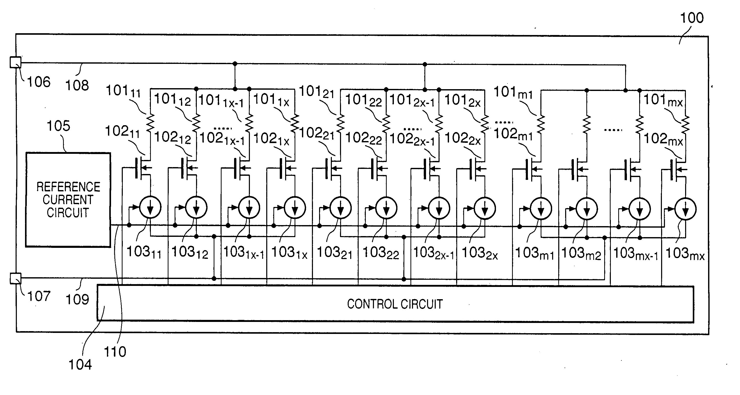
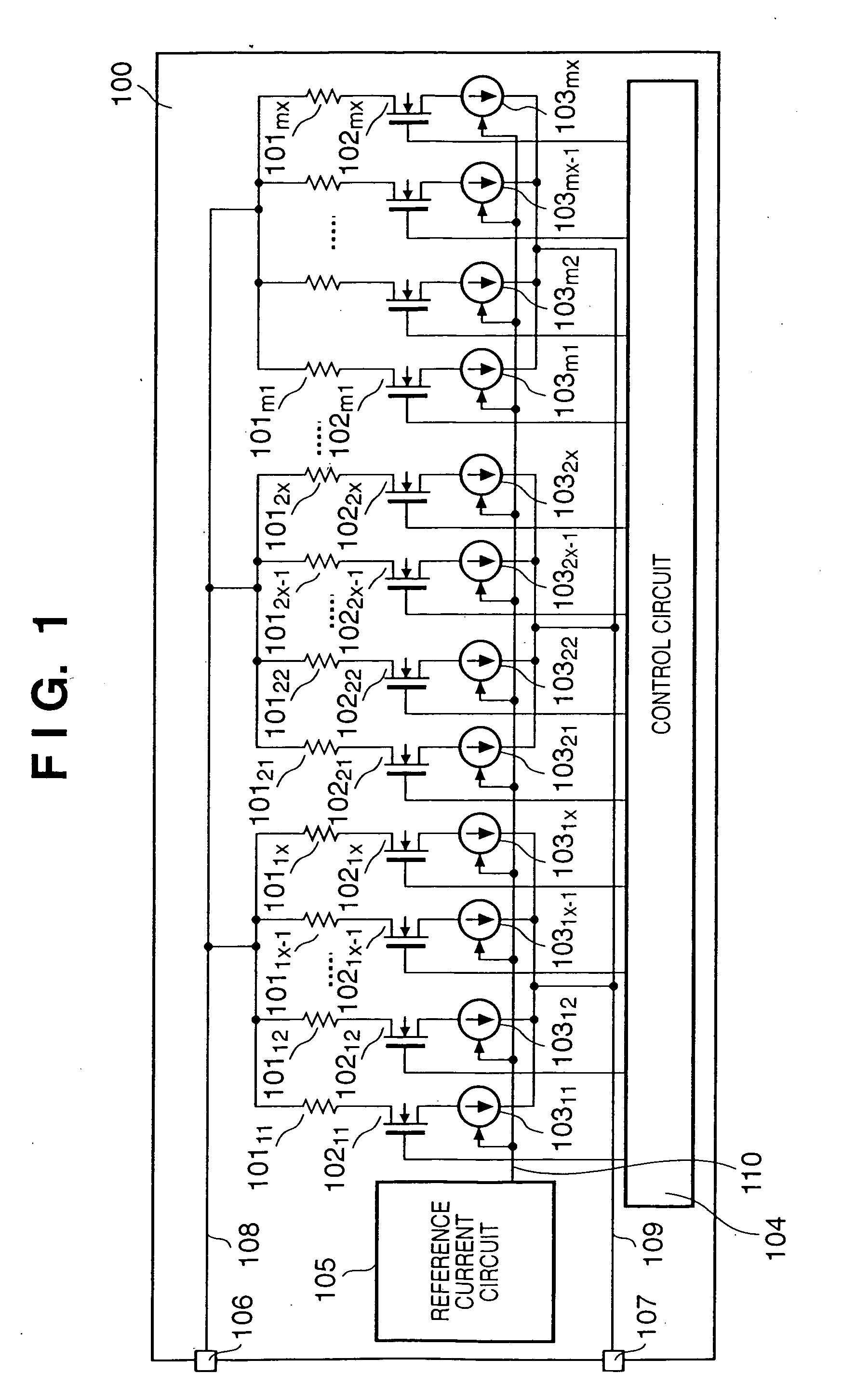
[0040]FIG. 1 is a circuit diagram for explaining the arrangement of a heater driving circuit mounted on the heater substrate of an inkjet printhead according to the first embodiment of the present invention.

[0041] In FIG. 1, reference numerals 10111 to 1011x denote heaters (heater resistors) for printing. A current is sent to each heater to generate heat, and a corresponding nozzle discharges an ink droplet. In the printhead using the heater substrate, orifices (nozzles) for discharging ink are arranged in correspondence with the respective heaters. The heaters 10111 to 1011x are divided into blocks 1 to m, and each block includes x heaters, and x NMOS transistors which are arranged in correspondence with the respective heaters. Reference numerals 10211 to 1021x denote NMOS transistors for ON / OFF-controlling energization to corresponding heaters. Reference numerals 10311 to 1031x denote constant current sources which are arranged in correspondence with the respective heaters. The c...

second embodiment

[0051]FIG. 4 is a circuit diagram showing an example in which the constant current source 103 of FIG. 1 according to the first embodiment is formed from NMOS transistors 40111 to 4011x. The same reference numerals as those in FIG. 1 denote the same parts, and a description thereof will be omitted.

[0052] The drains of the NMOS transistors 40111 to 4011x are respectively connected to the sources of switching NMOS transistors 10211 to 1021x. The gates of the NMOS transistors 40111 to 4011x receive a control signal 110 from a reference current circuit 105. Current values flowing through the respective heaters are controlled by the gate voltages of the NMOS transistors 40111 to 4011x which are controlled by the control signal 110 from the reference current circuit 105.

[0053] The operation of the NMOS transistors 40111 to 4011x in FIG. 4 will be explained with reference to FIGS. 5 and 6.

[0054]FIG. 5 is a graph showing an example of the general static characteristic of an NMOS transisto...

third embodiment

[0056]FIG. 7 is a circuit diagram showing an example in which the sources of NMOS transistors 70111 to 7011x are connected to the drains of the NMOS transistors 40111 to 4011x shown in FIG. 4, and two corresponding NMOS transistors are cascade-connected in series to form a constant current source 203 (FIG. 2). The same reference numerals as those in FIGS. 1 and 4 denote the same parts, and a description thereof will be omitted. The third embodiment will explain a structure of two transistors, but the present invention can also be applied to a structure of a larger number of transistors.

[0057] The gates of the NMOS transistors 70111 to 7011x are also connected to a reference current circuit 105. The NMOS transistors 70111 to 7011x operate as grounded-gate transistors, and fix the drain voltages of the NMOS transistors 40111 to 4011x on the basis of the potentials between the gates and sources of the NMOSs 70111 to 7011x. In this case, the reference current circuit 105 sets the gate ...


PUM


Abstract

A recording head having a plurality of recording elements comprises a plurality of switching elements, each provided in correspondence to each of the plurality of recording elements, constant current sources, each provided in correspondence to each of the plurality of recording elements, for flowing a constant current, and a constant current control circuit for controlling the constant current supplied from the constant current sources, and the recording elements are driven by N constant currents from the constant current sources.

Description

TECHNICAL FIELD [0001] The present invention relates to a recording head having a plurality of recording elements and a recording apparatus having the recording head. BACKGROUND ART [0002] There has conventionally been known an inkjet head which causes a heater arranged in the nozzle of a printhead to generate thermal energy, bubbles ink near the heater by using thermal energy, and discharges ink from the nozzle to print. FIG. 11 shows an example of a heater driving circuit in the inkjet head. [0003] To print at a high speed, heaters are desirably concurrently driven as many as possible to simultaneously discharge ink from many nozzles. However, the power supply capacity of the power supply of a printer apparatus is limited, and a current value which can be supplied at once is limited by, e.g., a voltage drop caused by the resistance of a wiring line extending from the power supply to the heater. For this reason, time divisional driving of driving a plurality of heaters in time divi...

Claims


Application Information

Patent Timeline
IPC IPC(8): B41J2/05
CPCB41J2/04541B41J2/04543B41J2/04553B41J2/0459B41J2/0458B41J2/04588B41J2/04568
Inventor HIRAYAMA, NOBUYUKI
Owner CANON KK
Why Eureka
Try Eureka