Image forming apparatus and method

a technology forming method, which is applied in the field of image forming apparatus, can solve the problems of increasing the circuit scale, increasing the cost of the apparatus, and reducing the stability of dot formation, so as to achieve cost reduction and maintain effective edge smoothing

Inactive Publication Date: 2005-09-29
CANON KK
View PDF3 Cites 18 Cited by
  • Summary
  • Abstract
  • Description
  • Claims
  • Application Information

AI Technical Summary

Benefits of technology

[0007] Accordingly, the present invention has an object to address the problems in application of the edge smoothing technique to an image forming apparatus using dark and light recording materials. More particularly, the object of the present invention is to enable cost reduction while maintaining effective edge smoothing.
[0008] Further, another object of the present invention is to stabilize formation of halftone dots caused by edge smoothing processing, thereby improving image quality.

Problems solved by technology

However, the application of smoothing processing to a light color signal, where edge portions are not conspicuous, does not greatly improve the image quality, but increases the circuit scale, thus increases the costs of the apparatus.
That is, when a large dot is formed so as to obtain a higher density, the stability of dot formation is increased, while when a small dot is formed so as to obtain a low density, the stability of dot formation is lowered (becomes unstable).

Method used


Image

  • Image forming apparatus and method
  • Image forming apparatus and method
  • Image forming apparatus and method

Examples


first embodiment

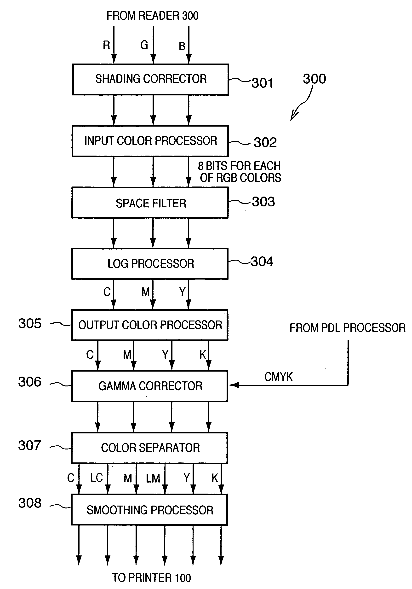
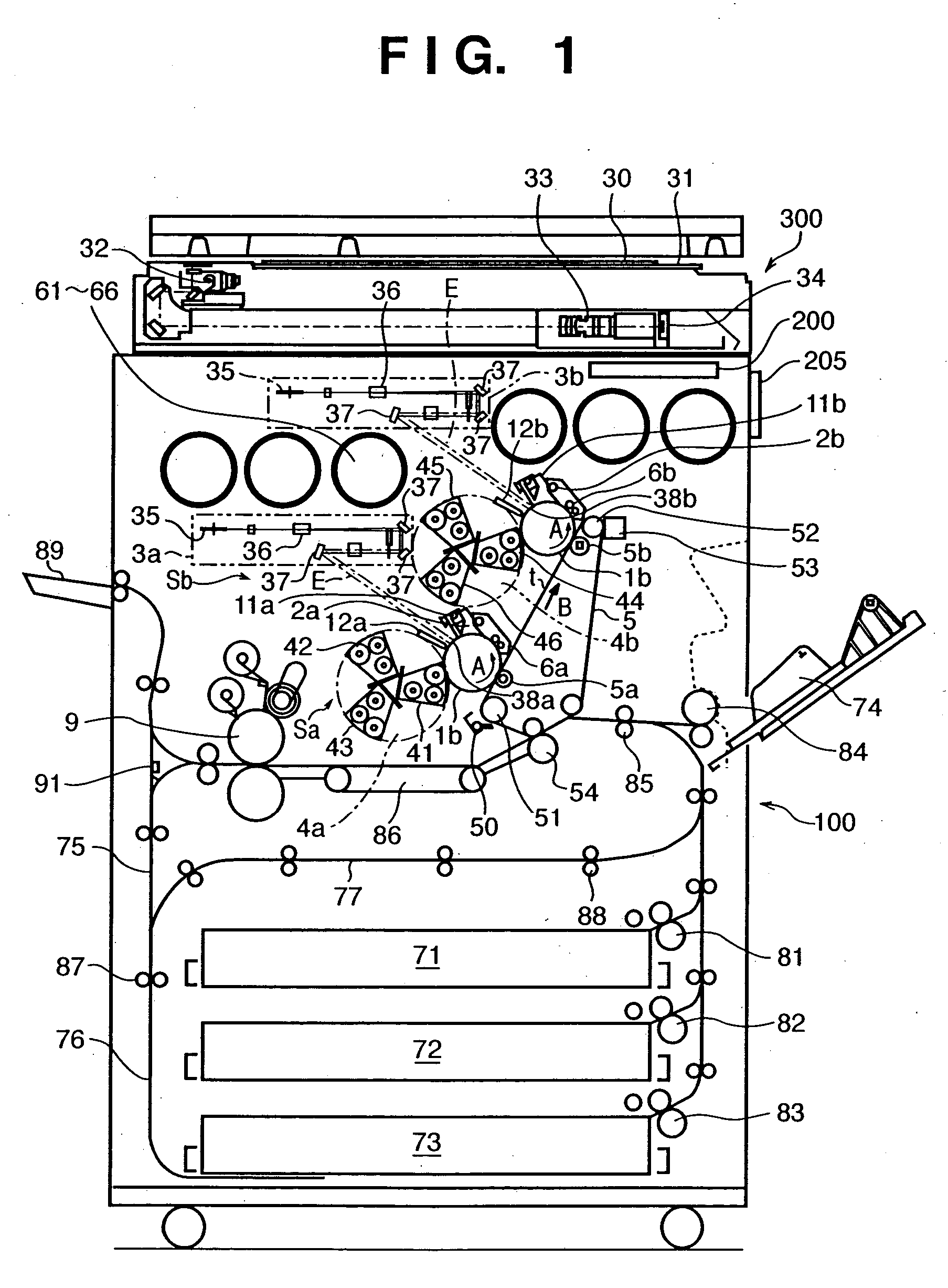
[0025]FIG. 1 is a schematic cross-sectional view of a full-color image forming apparatus (in this embodiment, a multifunction apparatus having a copy function, a printer function and a FAX function) according to a first embodiment. In the present embodiment, the apparatus has a digital color image reader 300 in a upper part and a digital color image printer 100 in a lower part.

[0026] In the reader 300, an original 30 placed on an original glass plate 31 is exposure-scanned by an exposure lamp 32. A reflected light image from the original 30 is collected via a lens 33 on a full-color CCD sensor 34, and color separation image signals are obtained. The color separation image signals are subjected to processing by a video processing unit (not shown) through an amplifier circuit (not shown), and outputted to the printer 100 via an image memory (not shown).

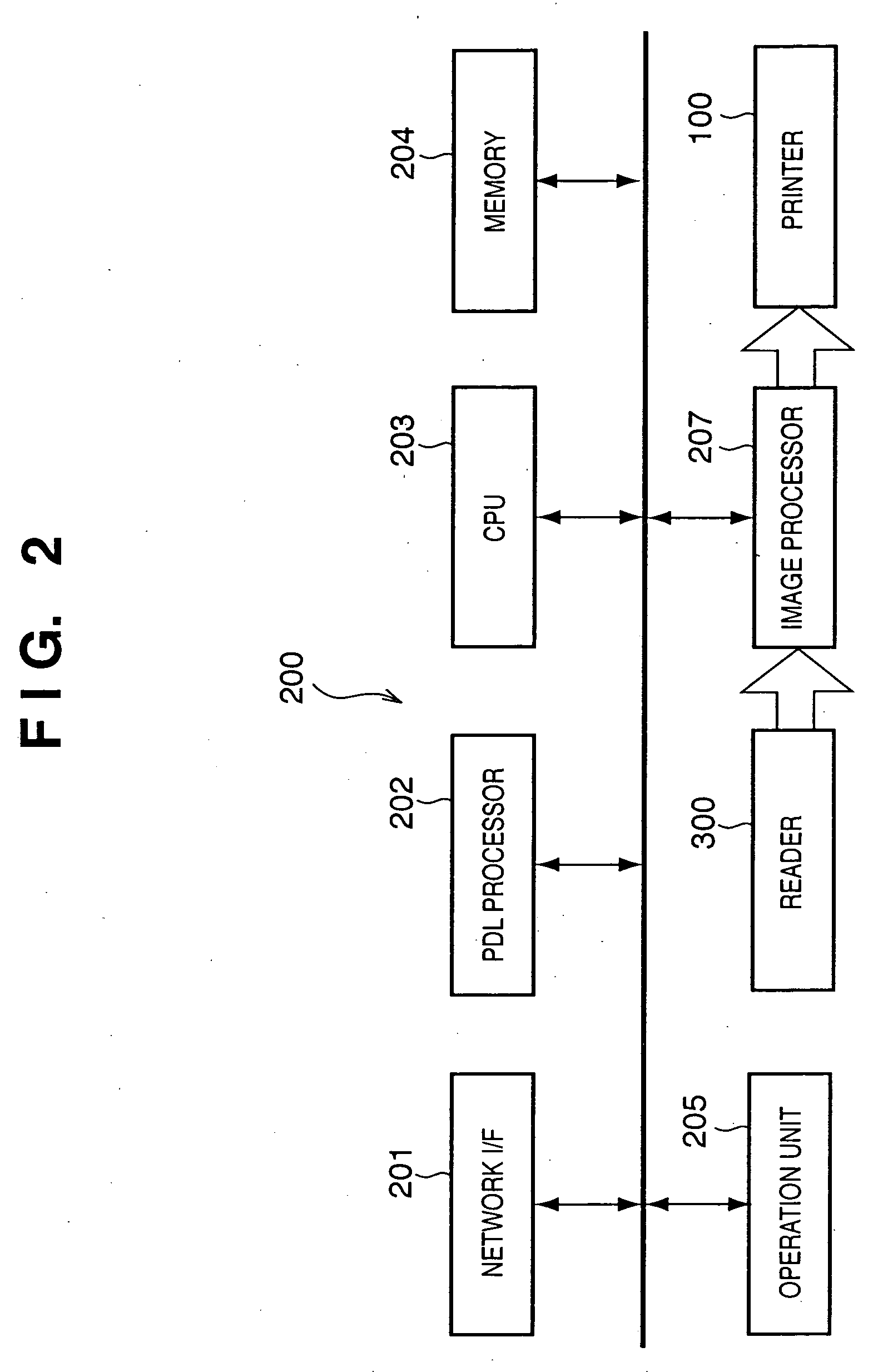
[0027] In addition to the signals from the reader 300, image signals from a computer and a FAX are transmitted to the printer 100. N...

second embodiment

[0063] In the above-described first embodiment, in a case where pixel replacement occurs in the smoothing processing circuit 800, the pixel value is replaced with an intermediate value (in FIGS. 7A to 7C, FFH→C0H, 00H→80H, 00H→40H). In the first embodiment, upon occurrence of pixel replacement, no interaction occurs among the color components. The pixel is replaced using an intermediate value of dark recording material, and image formation is performed. However, especially in an electrophotographic printer, dot formation of halftone dot becomes unstable as the signal level is lowered. Accordingly, in the second embodiment, the dot formation of pixel-replaced signal is stabilized by further replacing the pixel-replaced signal, generated by the smoothing on image signal corresponding to dark recording material, with an image signal for image formation using a combination of dark recording material and light recording material. That is, a halftone signal, newly generated by edge smooth...


PUM


Abstract

An image forming apparatus which performs image formation using plural color materials including dark color material and light color material for a hue generates color component signals corresponding to the respective plural color materials from an input image signal. Edge smoothing processing is performed on the respective color component signals except a color component signal corresponding to the light color material.

Description

FIELD OF THE INVENTION [0001] The present invention relates to an image forming apparatus used in a copier, a printer, a facsimile machine (hereinbelow, abbreviated to “FAX”) and the like, and more particularly, to image processing in an image forming apparatus which performs image formation using plural recording materials (ink or toner) of different densities in the same or similar color hue. BACKGROUND OF THE INVENTION [0002] Needs of the marketplace for printers are increased every year. Regarding color image formation, a 4-color image forming apparatus using 4 color ink or toner is popular, however, image forming apparatuses using increased number of colors of ink or toner have been proposed and realized. For example, an ink-jet printer which performs image formation using 6 inks including light cyan and light magenta inks as well as conventional cyan, magenta, yellow and black inks for the purpose of mitigation of graininess has been realized. Further, an electrophotographic p...

Claims


Application Information

Patent Timeline
Patent Type & Authority Applications(United States)
IPC IPC(8): B41J2/525G03G13/00B41J2/01G03G15/00G03G15/01H04N1/40H04N1/409H04N1/46H04N1/58H04N1/60
CPCH04N1/58H04N1/40087
Inventor NAMIKATA, TAKESHI
Owner CANON KK
Why Eureka
Try Eureka