Image compressing method and image compression apparatus

Inactive Publication Date: 2005-09-29
OLYMPUS CORP
View PDF2 Cites 32 Cited by
  • Summary
  • Abstract
  • Description
  • Claims
  • Application Information

AI Technical Summary

Problems solved by technology

Electronic cameras have become remarkably widespread, but a number of them reserve the number of captured records by lossy compressing image data due to the restricti

Method used


Image

  • Image compressing method and image compression apparatus
  • Image compressing method and image compression apparatus
  • Image compressing method and image compression apparatus

Examples


Example

[Embodiment 1]

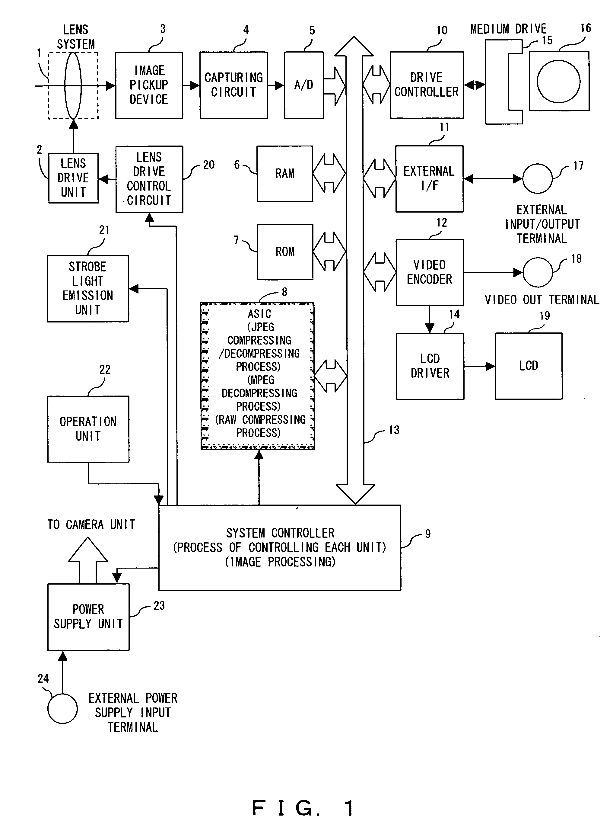
[0034]FIG. 1 shows the configuration of the electronic camera according to an embodiment 1 of the present invention.

[0035] The electronic camera has the function of lossless compressing the image data obtained from an image pickup device in a capturing operation, and recording the resultant data on a record medium, and also is an electronic camera having an image compression apparatus for performing the lossless compressing process (hereinafter referred to as a “RAW compressing process”.

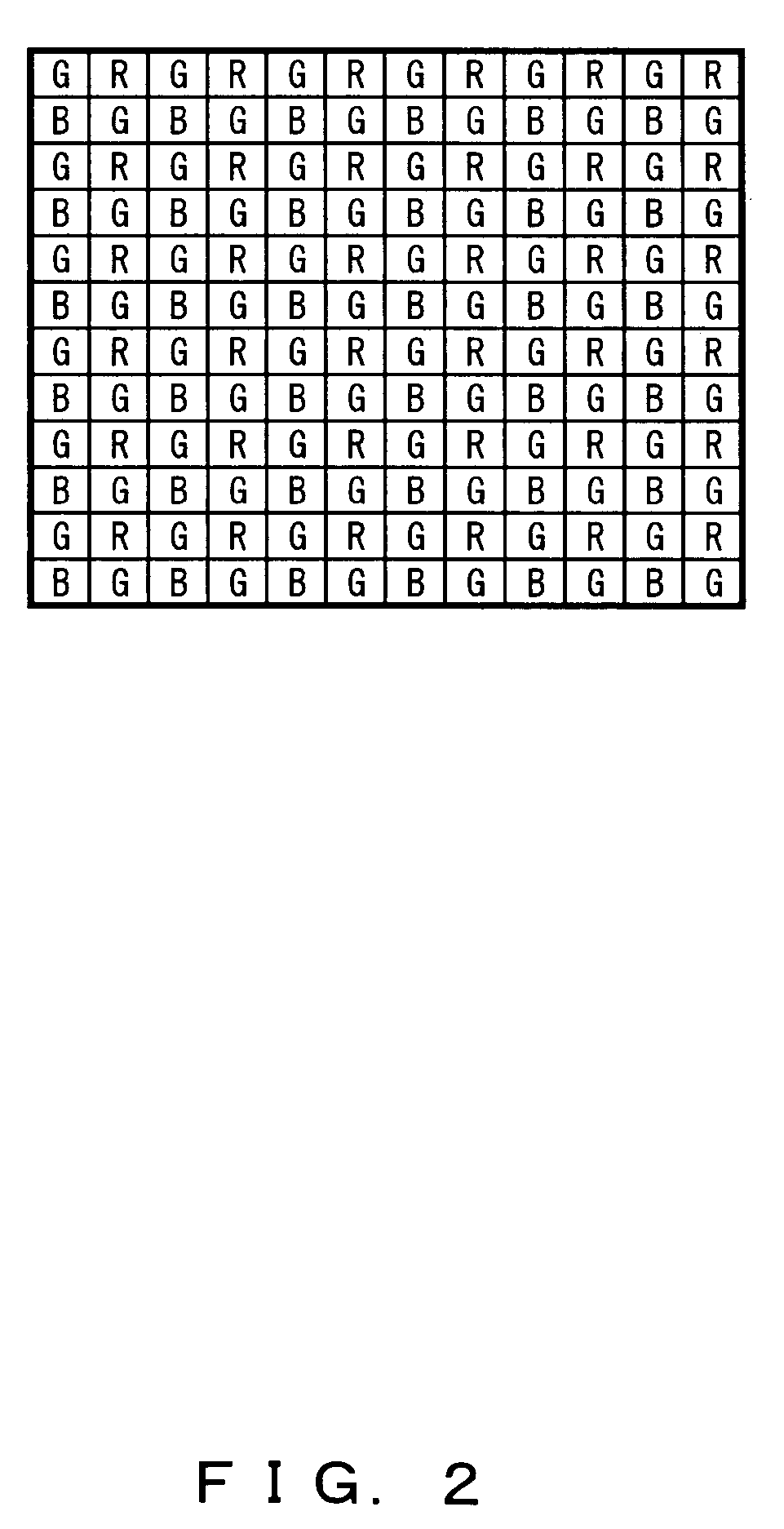
[0036] In FIG. 1, a lens system 1 is driven by a lens drive unit 2, and forms a subject image on an image pickup device 3. The image pickup device 3 optoelectronically transduces the formed subject image and outputs an electric signal. In the present embodiment, an image pickup device of a single plate type in which a color filter array of a Bayer array shown in FIG. 2 is applied as the image pickup device 3. A capturing circuit 4 performs a capturing process on the input electric si...

Example

[Embodiment 2]

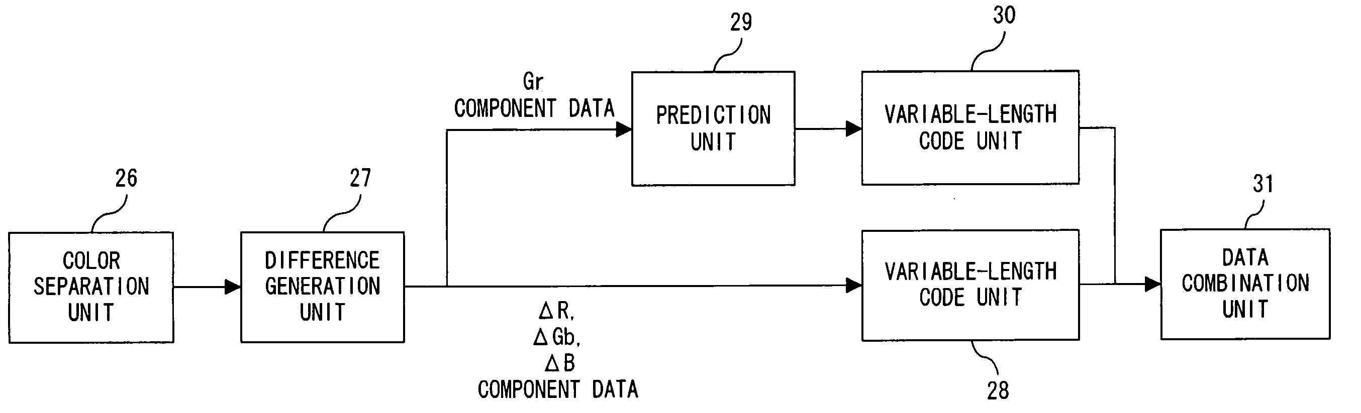
[0093] The present embodiment is different from the embodiment 1 only in RAW compressing process performed by the ASIC 8 under the control of the system controller 9. Therefore, only the RAW compressing process according to the present embodiment is explained below.

[0094]FIG. 10 is a block diagram showing the function relating to the RAW compressing process according to the present embodiment. Each component shown in FIG. 10 is realized by the ASIC 8 under the control of the system controller 9.

[0095] In FIG. 10, what are different from those shown in FIG. 3 are a positive / negative / absolute value extraction unit 46 provided between the difference generation unit 27 and the variable-length code unit 28, and a variable-length code unit 47. The positive / negative / absolute value extraction unit 46 separates and extracts each piece of difference data between the Gr component and each of the color components of R, B, and Gb into positive / negative data and absolute value da...

Example

[Embodiment 3]

[0124] Also according to the present embodiment, only the difference from the embodiment 1 is the RAW compressing process performed by the ASIC 8 under the control of the system controller 9. Therefore, only the RAW compressing process according to the present embodiment is explained here.

[0125]FIG. 15 is a block diagram of the function relating to the RAW compressing process according to the present embodiment. Each component shown in FIG. 15 is realized by the ASIC 8 under the control of the system controller 9

[0126] In FIG. 15 what is different from those shown in FIG. 3 is an offset calculation unit 51 and an offset subtraction unit 52 provided between the difference generation unit 27 and the variable-length code unit 28. The offset calculation unit 51 obtains offset data about each of the color components from the difference data between the Gr component and each of the color components of R, B, and Gb, and the offset subtraction unit 52 subtracts corresponding...


PUM


Abstract

An image compressing method includes: separating image data obtained from an image pickup device into each primary color component; obtaining difference data between each piece of image data of color components of colors other than a reference color in the image data separated into each primary color component, and the image data of the color component of the reference color; encoding the difference data to obtain a variable-length code; and encoding the image data of the color component of the reference color to obtain a predicted code.

Description

CROSS REFERENCE TO RELATED APPLICATIONS [0001] This application is based upon and claims the benefit of priority from the prior Japanese Patent Application No. 2004-093527, filed Mar. 26, 2004, the entire contents of which are incorporated herein by reference. BACKGROUND OF THE INVENTION [0002] 1. Field of the Invention [0003] The present invention relates to an image compressing method and an image compression apparatus for lossless compressing image data obtained from an image pickup device. [0004] 2. Description of the Related Art [0005] Electronic cameras have become remarkably widespread, but a number of them reserve the number of captured records by lossy compressing image data due to the restrictions on the recording capacity of an image record medium. [0006] There also is a recording system for enhancing the quality of playback images of image data by increasing the recorded data capacity per image while reducing a compression rate or performing a non-compressing process. On...

Claims


Application Information

Patent Timeline
IPC IPC(8): G06T9/00G06K9/36G06K9/46H04N1/41H04N5/91H04N5/917H04N5/92H04N9/07H04N9/79H04N11/04H04N19/50H04N19/593H04N19/90H04N19/91H04N101/00
CPCH04N1/64H04N19/176H04N19/186H04N19/593H04N19/136H04N19/13
Inventor ISHIKAWA, TAKASHIHIGURASHI, MASAKI
Owner OLYMPUS CORP
Why Eureka
Try Eureka