

Sliding bearing
- Summary
- Abstract
- Description
- Claims
- Application Information
AI Technical Summary
Benefits of technology
Problems solved by technology
Method used
Image

Examples
Embodiment Construction
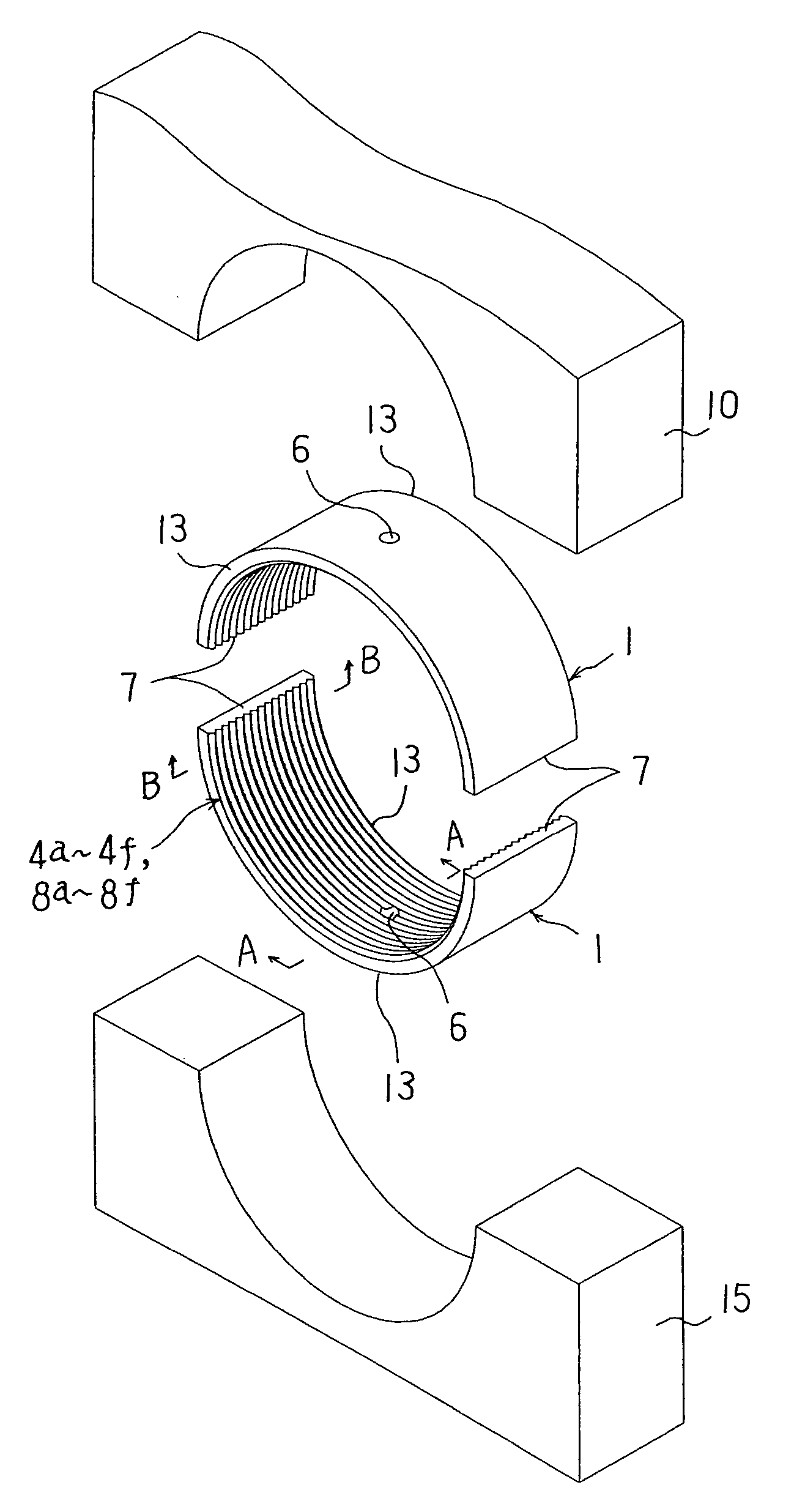
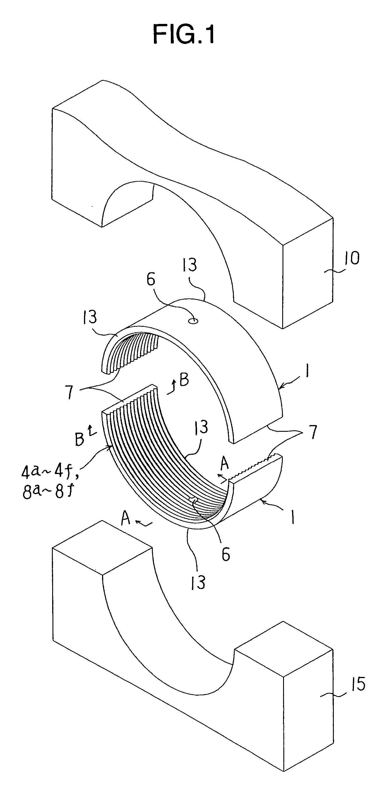
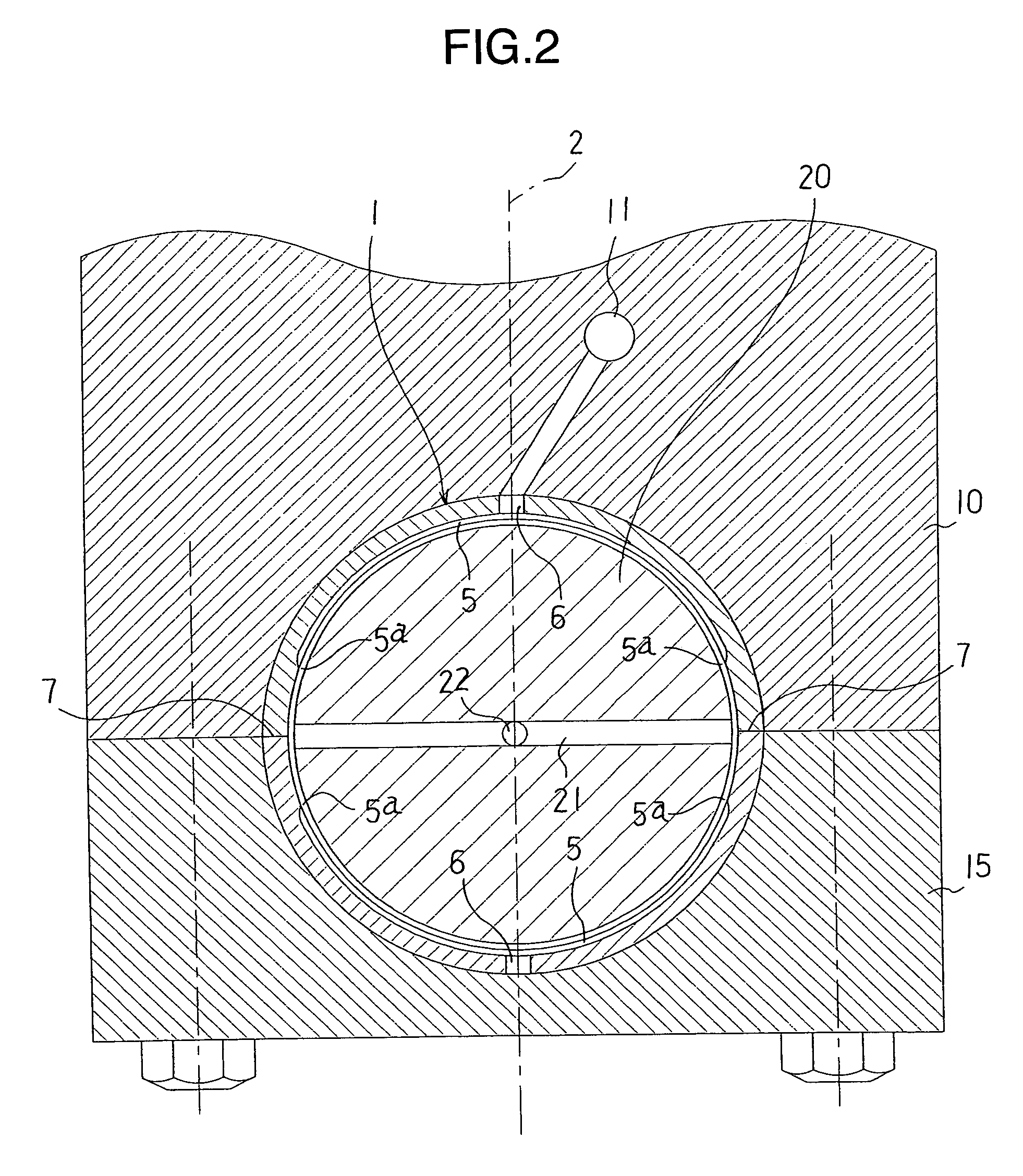
[0041] Hereinafter, an embodiment of the present invention will be explained with reference to FIGS. 1 to 6. FIG. 1 is an exploded perspective view showing relationship between housings 10 and 15 and a sliding bearing 1. FIG. 2 is a sectional view of a state in which a shaft 20 is supported by the sliding bearing 1, FIG. 3 is a sectional view (hatching is omitted) of the sliding bearing 1, FIGS. 4A and 4B, 4C and 4D, and 4E and 4F are enlarged sectional views taken along line A-A and line B-B in FIG. 1, respectively, FIG. 5 is a perspective view of the sliding bearing 1 in which crush relieves 3 are formed over an axial direction on an inner peripheral surface of both end parts 7 in a circumferential direction of the sliding bearing 1, and FIG. 6 is a perspective view of the sliding bearing 1 in which an oil groove 5 is formed on the inner peripheral surface along the circumferential direction. It should be noted that the above described drawings are schematic views of the sliding b...
PUM
 Abstract
Description
Claims
Application Information