Wiring device for optical fiber

a technology of optical fiber and wiring device, which is applied in the direction of optical fiber cables between relatively moving parts, instruments, lenses, etc., can solve the problems of increasing the loss of transmission, reducing the reliability of signal transmission, and the remaining length portion of optical fiber cables, so as to improve the performance of connection work

Inactive Publication Date: 2005-09-29
MATSUSHITA ELECTRIC WORKS LTD
View PDF0 Cites 116 Cited by
  • Summary
  • Abstract
  • Description
  • Claims
  • Application Information

AI Technical Summary

Benefits of technology

[0006] The present invention is contrived to solve the above problems, and it is an object of the present invention to provide a wiring device for

Problems solved by technology

However, when the optical fiber cable is bent in a radius of curvature smaller than a permitted minimum radius of curvature, the transmitting loss increases or the reliability of a signal transmission decreases.
As a result, there are problems in that it is need to manage the radius of curvat

Method used


Image

  • Wiring device for optical fiber
  • Wiring device for optical fiber
  • Wiring device for optical fiber

Examples


Embodiment Construction

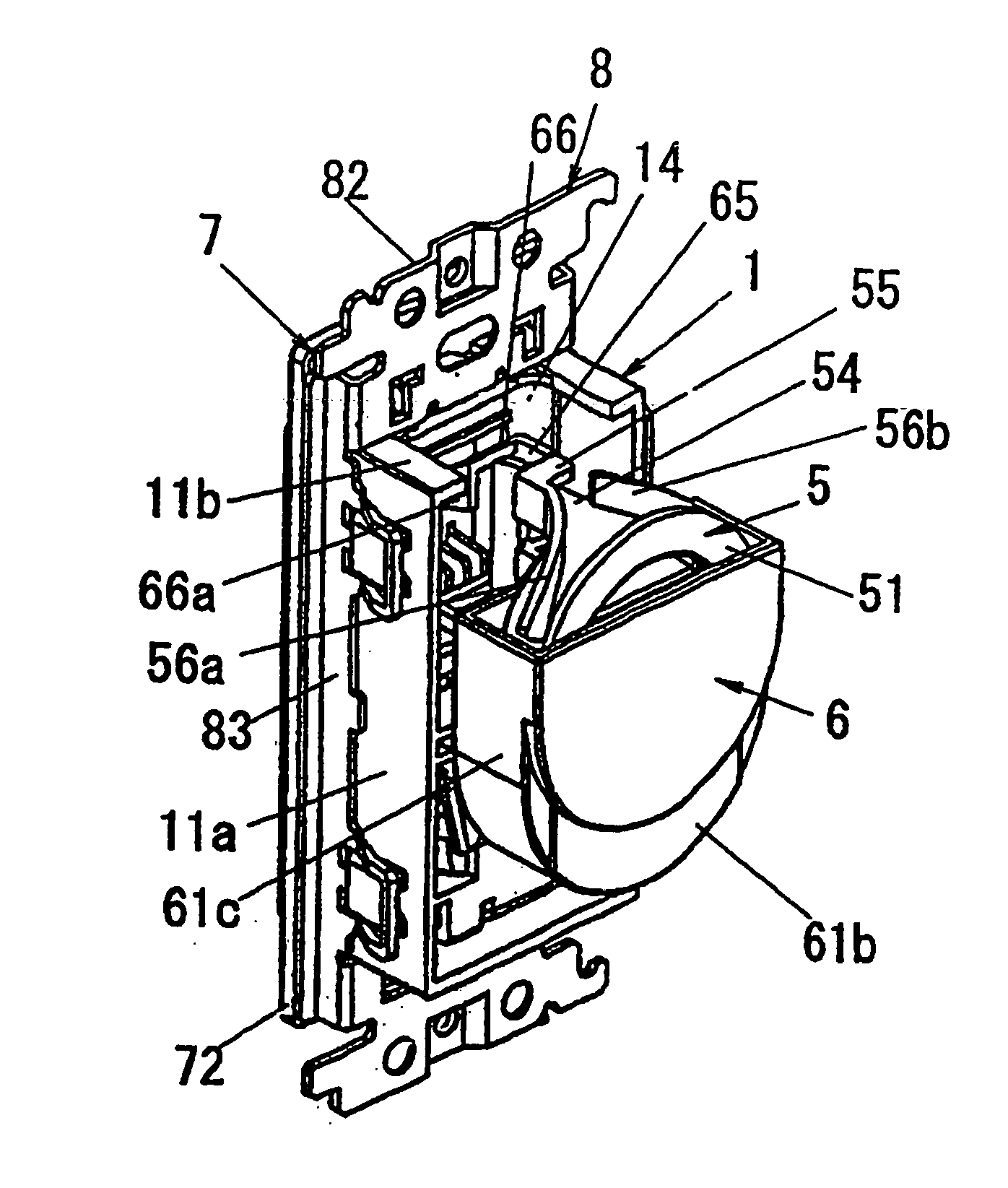
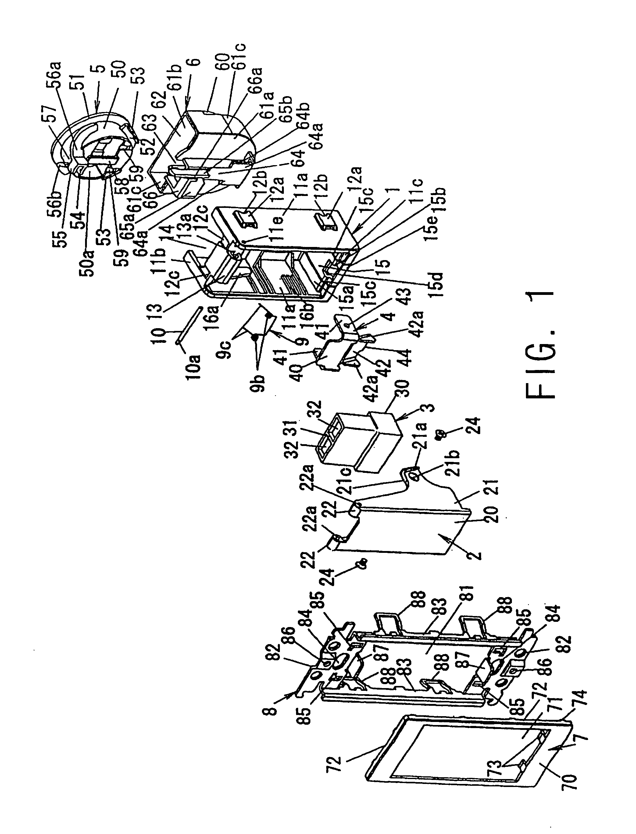
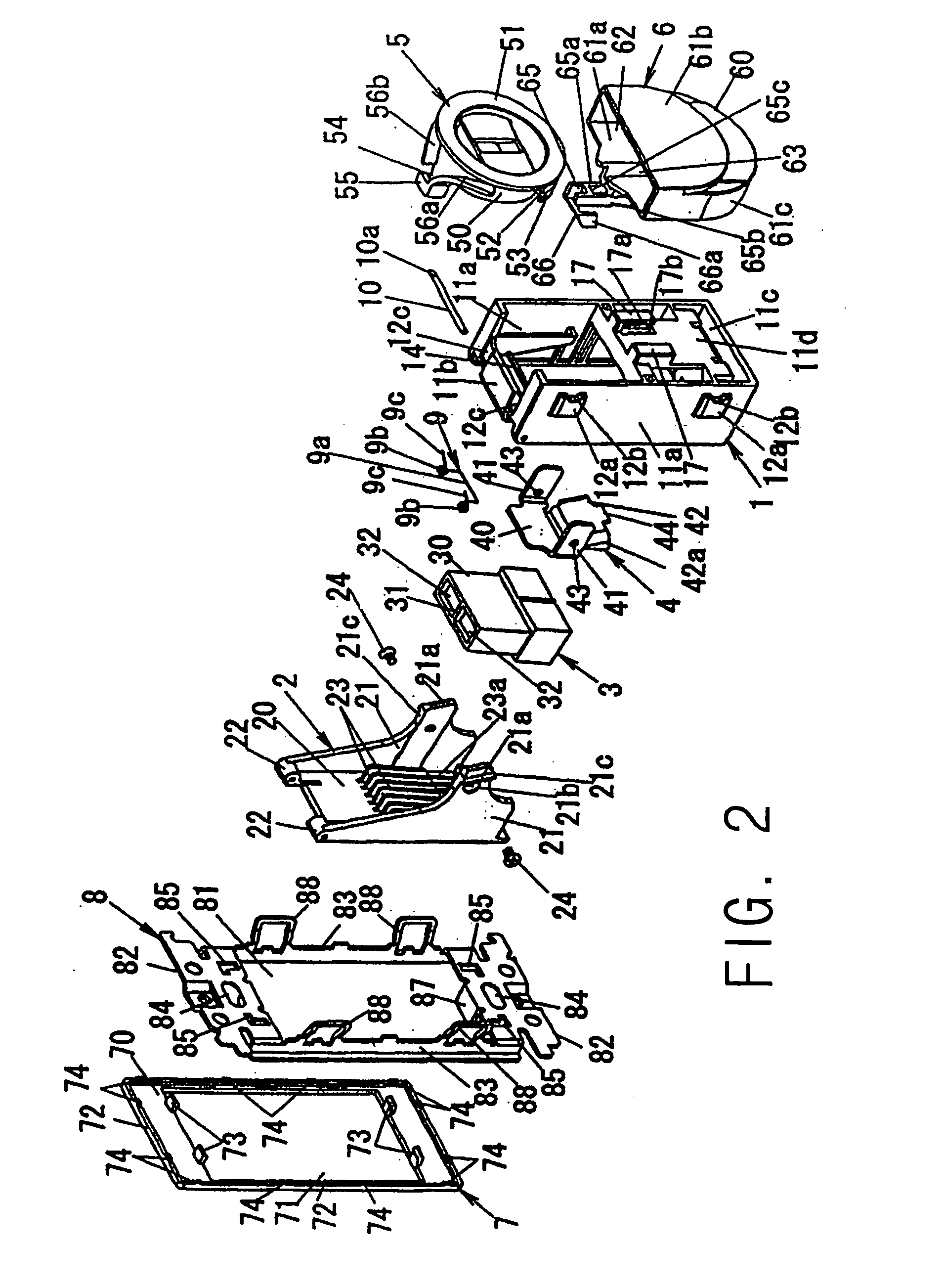
[0023] Hereinafter, embodiments of the present invention will be described in detail with reference to the FIGS. 1 to 10 such that the embodiments can be easily put into practice by those skilled in the art. However, since the present invention can be embodied in various forms, the present invention is not limited to the embodiments described below.

[0024] Further, in the detailed description of the present invention to be described below, if it is not specifically mentioned, in case that the left, right, top and bottom directions are prescribed, the front face of FIG. 3A becomes the front side. Therefore, the right edge of FIG. 3B becomes the rear end.

[0025] As shown FIGS. 1 to 3, a wiring device according to an embodiment of the present invention comprises an window-opening 81 having the same dimensions as a mounting frame to which three wiring devices being each one module in the shape of the big square standardized in JIS (Japanese Industrial Standard) is attached, a metallic m...


PUM


Abstract

There is provided wiring device for optical fiber capable of increasing the performance of connection work of an optical fiber cable without deteriorating a signal transmitting properties of the optical fiber cable. The wiring device comprise a plug receptacle main body which is mounted on a mounting opening opened in the outer surface of a building, a receptacle being provided to the plug receptacle main body and having a plug connection hole facing an outside of the plug receptacle main body, a winder including a winding body which has an outer circumferential surface of radius of curvature larger than the permitted minimum radius of curvature of an optical fiber cable wired to the inside of a building and connected to the receptacle and on which a core wire of the optical fiber cable is wound, and a retainer being provided on the plug receptacle main body to maintain the winder inner side of a building, in which the receptacle for optical fiber and the winder are arranged in parallel with each other in the front-back direction, and pressing pieces are formed integrally with the winder and the retainer for contacting the bent portion of the core wires to prevent the bent portion from being expanded.

Description

BACKGROUND OF THE INVENTION [0001] (a) Field of the Invention [0002] The present invention relates to a wiring device for optical fiber, which uses an optical plug receptacle for connecting an optical fiber cable introduced inside the wall or under the floor of a building. [0003] (b) Description of the Related Art [0004] Conventionally, a wiring device for optical fiber in which an optical fiber cable wired inside a building is introduced into a flush box laid in the wall surface of the building and an optical plug receptacle being attached to a flush box using a mounting frame standardized based on a flush type wiring device is used is disclosed (for example, see Japanese Examined Patent Application Publication No. 2,793,183). [0005] In the aforementioned wiring device in which an optical plug receptacle is attached to a flush box laid in the wall surface, in order to receive a remaining length portion of the optical fiber cable being introduced into the empty space of the flush bo...

Claims


Application Information

Patent Timeline
IPC IPC(8): G02B6/00G02B6/24G02B6/36G02B6/44H02G3/02H02G11/00
CPCG02B6/4466G02B6/4457G02B6/475H02G3/36
Inventor TANAKA, SATORUYOSHIDA, MASARUKINEKAWA, YASUICHISHOGAKI, YOSHIHIRO
Owner MATSUSHITA ELECTRIC WORKS LTD
Why Eureka
Try Eureka