Integrated multi-rail imaging system

a multi-rail imaging and imaging system technology, applied in the field of small animal imaging systems, can solve the problems of difficult alignment of needle guidance devices, laborious and time-consuming process, and inability to straightforward repeat the position of different animals

Active Publication Date: 2005-09-29
FUJIFILM SONOSITE
View PDF74 Cites 23 Cited by
  • Summary
  • Abstract
  • Description
  • Claims
  • Application Information

AI Technical Summary

Benefits of technology

[0010] The imaging system of the present invention allows for productive imaging of small-animals. In one example, the imaging system can include a plurality of elongated rails, a scanhead assembly, and a small animal mount assembly. In another example, a needle injection assembly is also included in the imaging system.

Problems solved by technology

One disadvantage with present positioning systems for animals is that straightforward repeatability of position with different animals is not possible.
For example, during injections procedures, a common problem has been the challenge of aligning a needle guidance device, which injects very small quantities of fluid, with a UBM scanhead device.
Consequently, this is a laborious and time-consuming process, which is aggravated by the need to move both devices away from an animal handling device, upon which a small animal is mounted, when a different animal is to be scanned.
To date, no device serves each of the needs outlined to enable the safe and effective delivery of anaesthesia to small animals, the physiological monitoring of the immobilized subject, the capacity for a range of motion, and the ability to successfully externalize embryos on a specialized table.

Method used


Image

  • Integrated multi-rail imaging system
  • Integrated multi-rail imaging system
  • Integrated multi-rail imaging system

Examples


Embodiment Construction

[0081] The present invention is more particularly described in the following examples that are intended as illustrative only since numerous modifications and variations therein will be apparent to those skilled in the art. Thus the embodiments of this invention described and illustrated herein are not intended to be exhaustive or to limit the invention to the precise form disclosed. They are chosen to describe or to best explain the principles of the invention and its application and practical use to thereby enable others skilled in the art to best utilize the invention. As used in the specification and in the claims, “a,”“an,” and “the” can mean one or more, depending upon the context in which it is used. The preferred embodiment is now described with reference to the figures, in which like numbers indicate like parts throughout the figures.

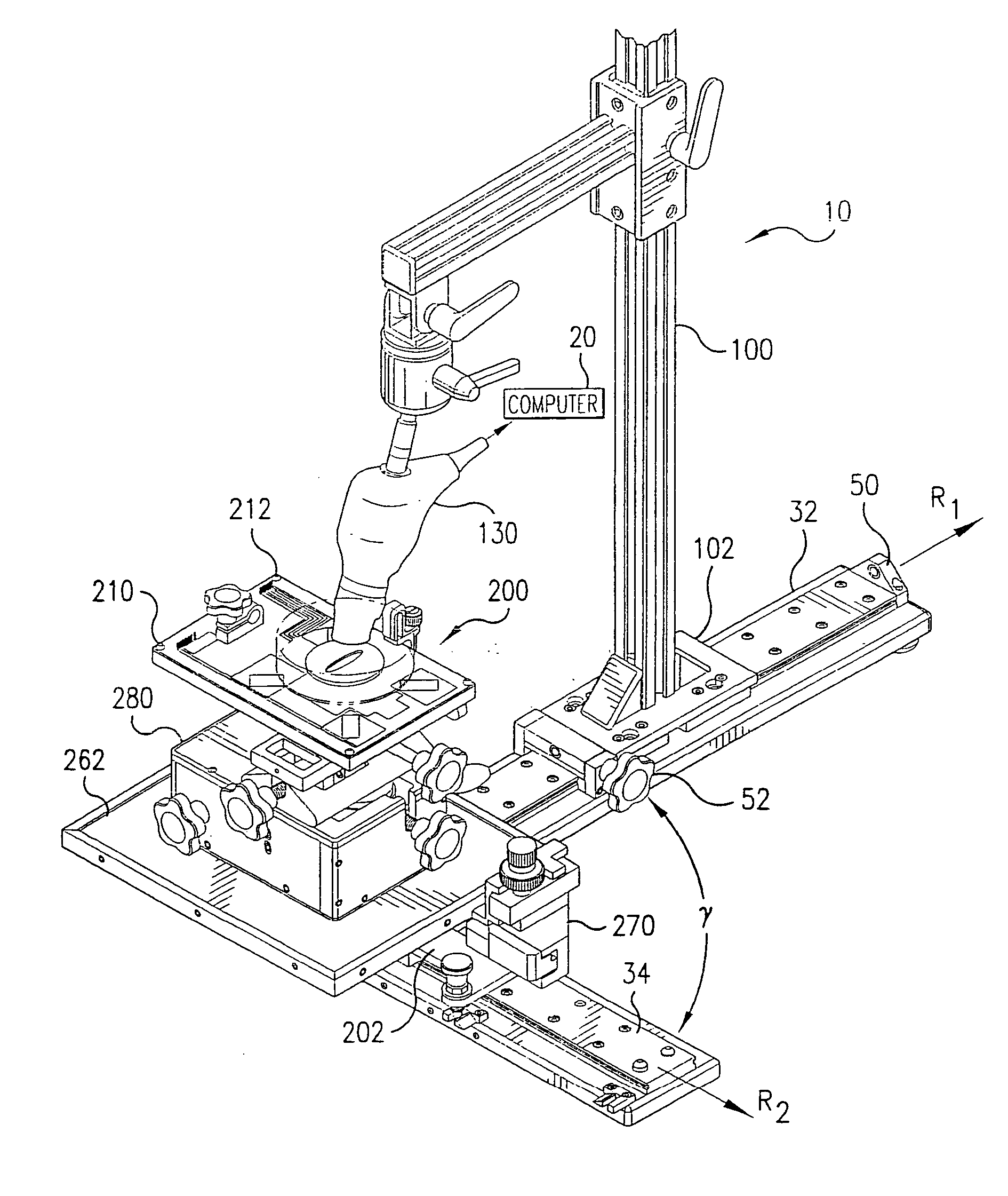
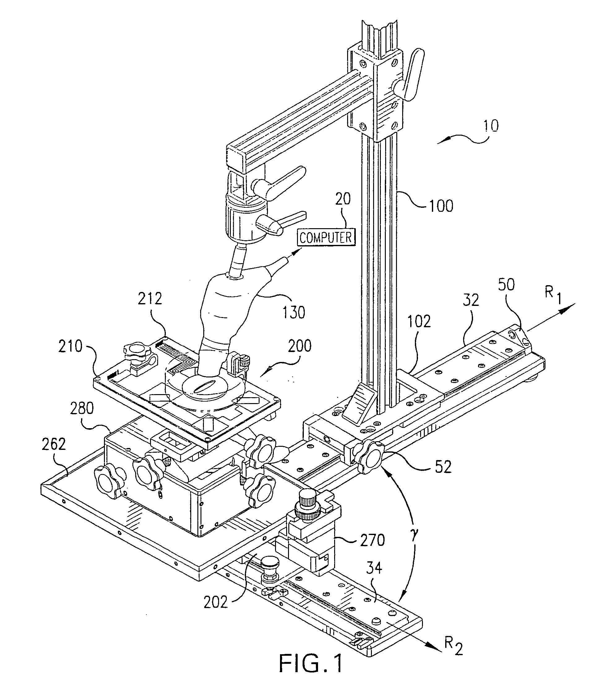
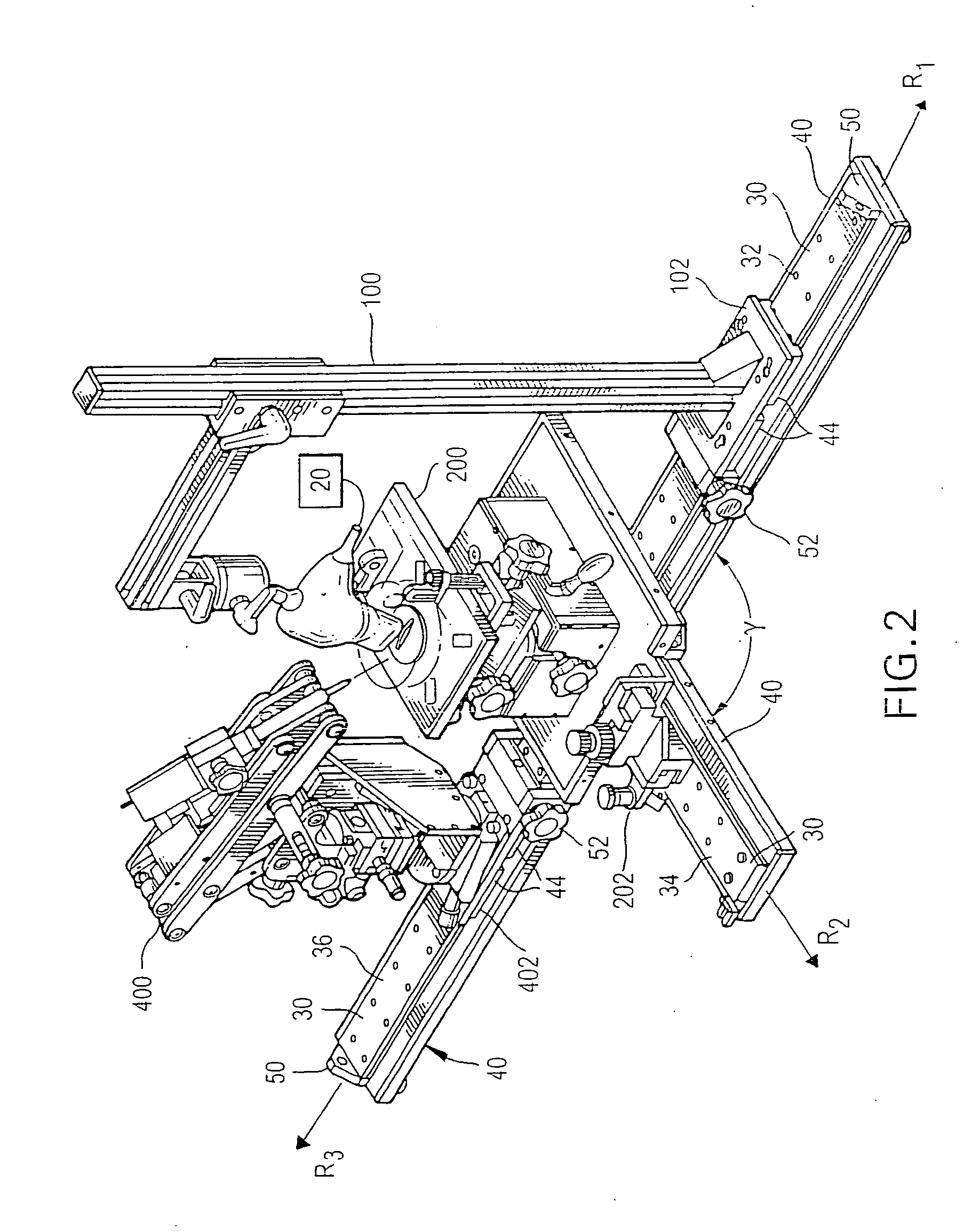
[0082] Referring to FIG. 1, one embodiment of an integrated multi-rail imaging system 10 of the present invention is shown. The imaging system...


PUM


Abstract

The imaging system can comprise a plurality of elongated rails, a scanhead assembly, and a small animal mount assembly. The scanhead assembly is selectively mounted onto a first rail and is constructed and arranged for movement in a linear bi-directional manner along the longitudinal axis of the first rail. The small-animal mount assembly is selectively mounted onto a second rail and is constructed and arranged for movement in a linear bi-directional manner along the longitudinal axis of the second rail. The second rail being mounted relative to the first rail such that the longitudinal axis of the second rail is at an angle to the longitudinal axis of the first rail. The imaging system can also comprise a needle injection assembly that is selectively mounted onto the third rail and is constructed and arranged for movement in a linear bi-directional manner along the longitudinal axis of the third rail. The third rail being mounted relative to the second rail and the first rail such that the longitudinal axis of the third rail is substantially coaxial to the longitudinal axis of the first rail. Alternatively, the needle injection assembly is mounted onto the first rail, such that the second rail is positioned therebetween the needle injection assembly and the scanhead assembly.

Description

CROSS-REFERENCE TO RELATED APPLICATIONS [0001] This application is a continuation-in-part of U.S. application Ser. No. 10 / 683,168 filed on Oct. 10, 2003 which claims priority to and the benefit of U.S. Provisional Application No. 60 / 417,167 filed on Oct. 10, 2002; U.S. Provisional Application No. 60 / 468,959 filed on May 9, 2003; U.S. Provisional Application No. 60 / 417,185, filed on Oct. 10, 2002; and U.S. Provisional Application No. 60 / 468,960, filed on May 9, 2003, all of which are incorporated in their entirety in this document by reference.BACKGROUND OF THE INVENTION [0002] 1. Field of the Invention [0003] The present invention relates to a small-animal imaging system, and more particularly to a multi-rail imaging system for maintaining a desired image plane during an imaging session. [0004] 2. Description of the Prior Art [0005] Over the past few years researchers in disciplines as diverse as neuroscience, developmental biology, genetics, and oncology have struggled with the cha...

Claims


Application Information

Patent Timeline
Patent Type & Authority Applications(United States)
IPC IPC(8): A61B5/05A61B6/12A61B8/08A61B8/14
CPCA61B6/12A61B8/0833A61B8/0841A61B6/508A61B5/0555A61D3/00A61B8/4209A61B5/055A61B6/44A61B8/40A61B8/4461A61B90/11A61B6/0487A61B6/032
Inventor ZAN, LEO
Owner FUJIFILM SONOSITE
Why Eureka
Try Eureka