Airplane emergency navigational system

a navigation system and aircraft technology, applied in the direction of navigation instruments, process and machine control, instruments, etc., can solve the problems of aircraft damage, one or more aircraft systems malfunctioning, and inability to enter data in time, so as to prevent corruption and/or damage

Inactive Publication Date: 2005-09-29
TURUNG BRIAN E
View PDF14 Cites 39 Cited by
  • Summary
  • Abstract
  • Description
  • Claims
  • Application Information

AI Technical Summary

Benefits of technology

[0028] It is yet a further and / or alternative object of the present invention to provide an emergency navigational system that can be manually and / or remotely caused to take full or partial navigational control of an aircraft.
[0029] It is yet a further and / or alternative object of the present invention to provide an emergency navigational system that can be manually and / or remotely caused to fully or partially release navigational control of an aircraft.
[0030] It is another and / or alternative object of the present invention to provide an emergency navigational system that can be loaded with data while the aircraft is on the ground and / or in flight.
[0031] It is still another and / or alternative object of the present invention to provide an emergency navigational system that includes security measures to prevent corruption and / or damage of data in the emergency navigational system.

Problems solved by technology

Such actual and / or perceived emergency situation can include, but are not limited to, hijacking, injured and / or unconscious pilots and / or authorized personnel, adverse weather conditions, close proximity of other aircraft, improper flight path, improper airspeed, improper navigational commands, improper altitude, improper aircraft orientation, advancing projectiles, non-entry of timely data by pilot and / or authorized personnel, damage to the aircraft, failure and / or malfunction of one or more systems on the aircraft (e.g. electrical problems, hydraulic problems, communication problems, etc.); fuel problems (e.g. low fuel, fuel loss, etc.); passenger illness, lost communications with ground control; aircraft damage; and / or the like.
In one aspect of this embodiment, the attempted removal of the emergency navigational system and / or improper enabling and / or disabling ful or partial the navigational control of the aircraft by the emergency navigational system constitutes an actual emergency situation resulting in the activation of the emergency navigational system.

Method used


Image

  • Airplane emergency navigational system
  • Airplane emergency navigational system
  • Airplane emergency navigational system

Examples


Embodiment Construction

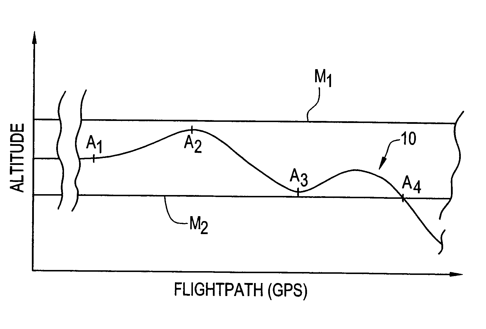
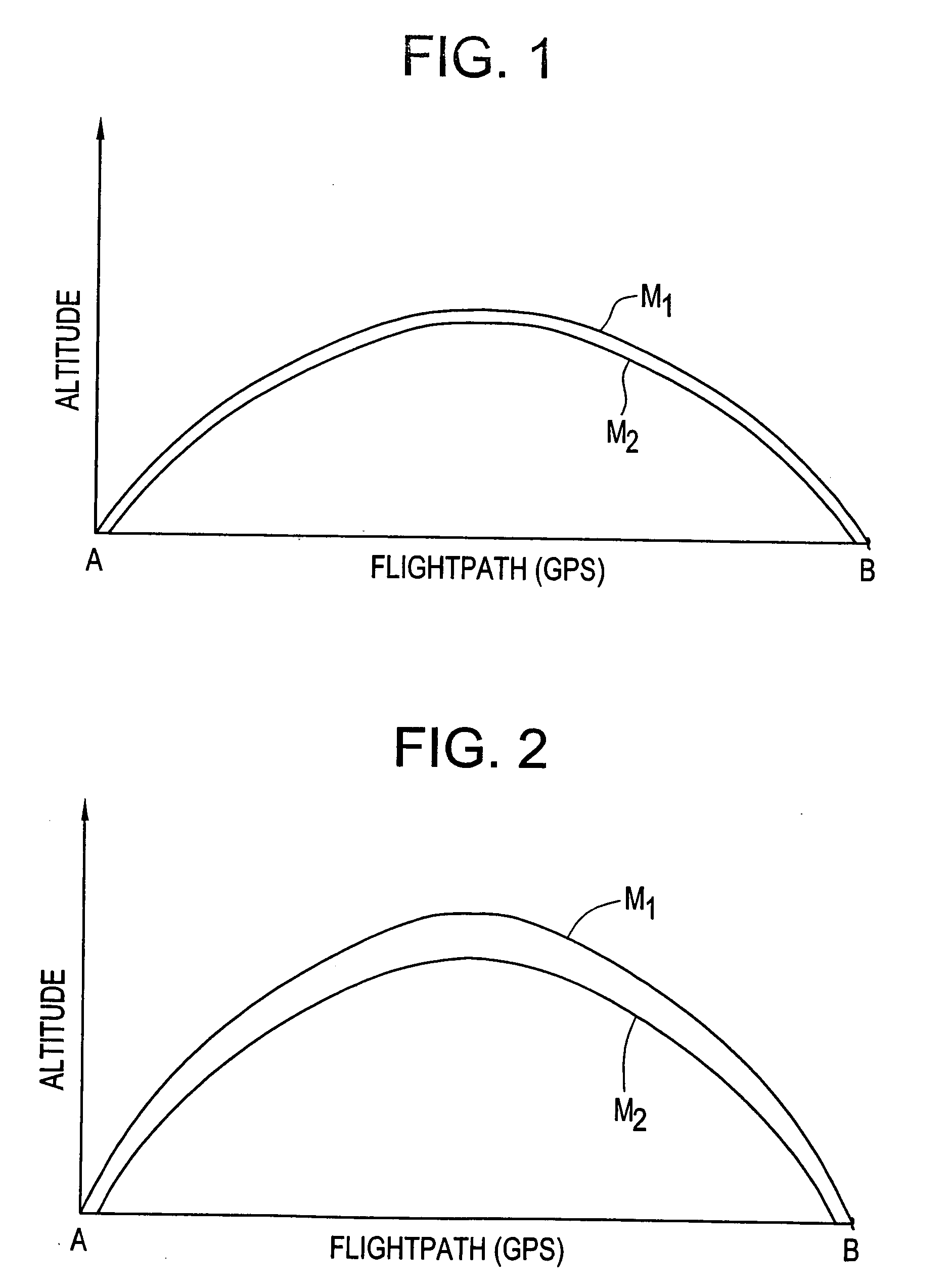
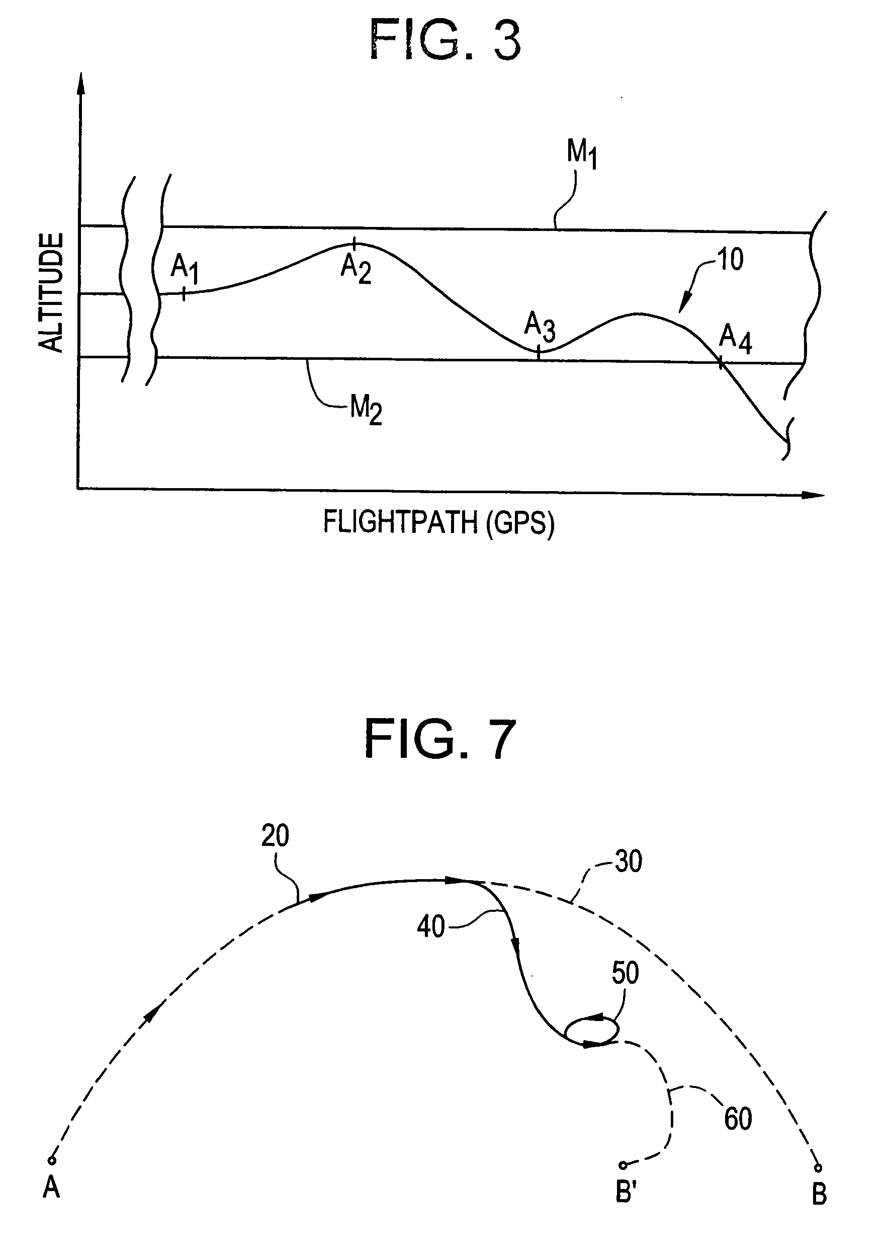
[0047] Referring to the drawings, wherein the showings are for the purpose of illustrating the preferred embodiments of the invention only and not for the purpose of limiting same, FIG. 1 illustrates a predefined flight path of an aircraft from a first destination A to a second destination B. The predefined flight path defines the desired and acceptable flight path of the aircraft from the first to the second destination. This predefined flight path is used by the emergency navigational system to compare the present position of an aircraft to the predefined flight data. The emergency navigational system uses this information to determine whether or not the aircraft has unacceptably deviated from the predefined flight path.

[0048] The emergency navigational system is typically incorporated into the navigational systems of the aircraft which are located in the cockpit of the aircraft. As can be appreciated, one or more components of the emergency navigational system can be located in ...


PUM


Abstract

An emergency navigational system that monitors the navigation of an aircraft by comparing actual flight parameter data to predefined flight parameter data to thereby determine if the actual flight parameter data deviates beyond a defined value, and if so, activating a navigational controller to at least partially control the navigation of the aircraft.

Description

[0001] This patent application claims priority on co-pending U.S. Provisional Application Ser. No. 60 / 322,184 filed Sep. 13, 2001, entitled “Airplane Emergency Navigational System”, and on PCT Patent Application No. PCT / US02 / 28617 filed Sep. 10, 2002, entitled “Airplane Emergency Navigational System”.[0002] The present invention pertains to aircraft, and more particularly to emergency navigational systems for aircraft. INCORPORATION BY REFERENCE [0003] U.S. Pat. Nos. 6,443,399; 6,430,480; 6,405,107; 6,259,976; 6,201,482; 6,182,005; 6,178,363; 6,064,939; 6,041,273; 6,002,347; and 5,157,615; and United States Patent Publication Nos. US 2002 / 0080059 A1; US 2002 / 0069019 A1; and US 2002 / 0002428 A1 are incorporated by reference to illustrate various collision avoidance systems, warning systems, guidance and navigational systems, and data informational systems that can be interfaced with and / or incorporated into the present invention. These patents and patent publications also provide back...

Claims


Application Information

Patent Timeline
Patent Type & Authority Applications(United States)
IPC IPC(8): B64C1/00B64D45/00G01C5/00G05D1/00
CPCB64D45/0015G05D1/0061G01C5/005B64D2045/0055B64D45/0031B64D45/0059
Inventor TURUNG, BRIAN E.
Owner TURUNG BRIAN E
Why Eureka
Try Eureka