Unit for filling containers with products, in particular, pharmaceutical products

a technology for filling containers and products, applied in the direction of counting objects on conveyors, packaging goods types, instruments, etc., can solve the problems of insufficient filling of small bars, many limitations and drawbacks, and easy to happen, so as to facilitate maintenance operations, facilitate safe and rapid feeding of tablets, and simple structure

Inactive Publication Date: 2005-10-06
IMA IND MASCH AUTOMATICHE SPA
View PDF23 Cites 52 Cited by
  • Summary
  • Abstract
  • Description
  • Claims
  • Application Information

AI Technical Summary

Benefits of technology

[0038] In particular, an object of the present invention is to propose a unit, which ensures a rapid and safe feeding of the tablets to be packaged to the counting area, keeping a simple structure, which is easily accessible for maintenan

Problems solved by technology

The machines of the above described type reach considerable operation speed (even 300-400 bottles filled in a minute), however they present many limits and drawbacks.
First of all, the seats of the small bars are not always correctly filled during the passage below the hopper, because the tablets of irregular shape can be arranged in an incorrect position with respect to the relative seat, or some seats can be occupied by tablet fragments or by a non entire tablet.
Therefore, it can quite easily happen that a bottle is filled in an incomplete, or incorrect way.
Moreover, if a defective or partially damaged tablet is detected, the above described machines are not able to reject a single defective table and therefore it is necessary to reject the whole bottle containing the defective tablet, which obviously results in considerable economic consequences.
Further drawbacks result from the complexity of the size change over operations in order to adapt the machine to operate with tablets and/or bottles of different size

Method used


Image

  • Unit for filling containers with products, in particular, pharmaceutical products
  • Unit for filling containers with products, in particular, pharmaceutical products
  • Unit for filling containers with products, in particular, pharmaceutical products

Examples


Embodiment Construction

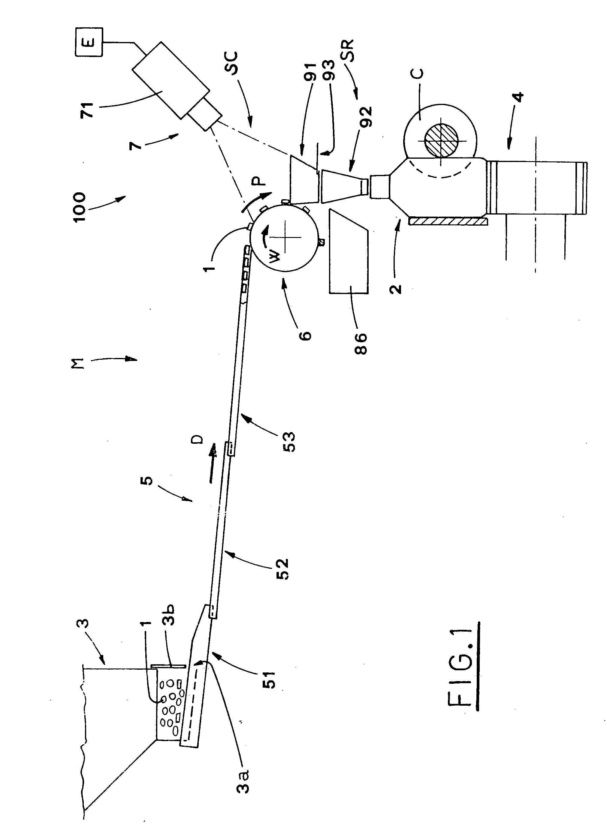
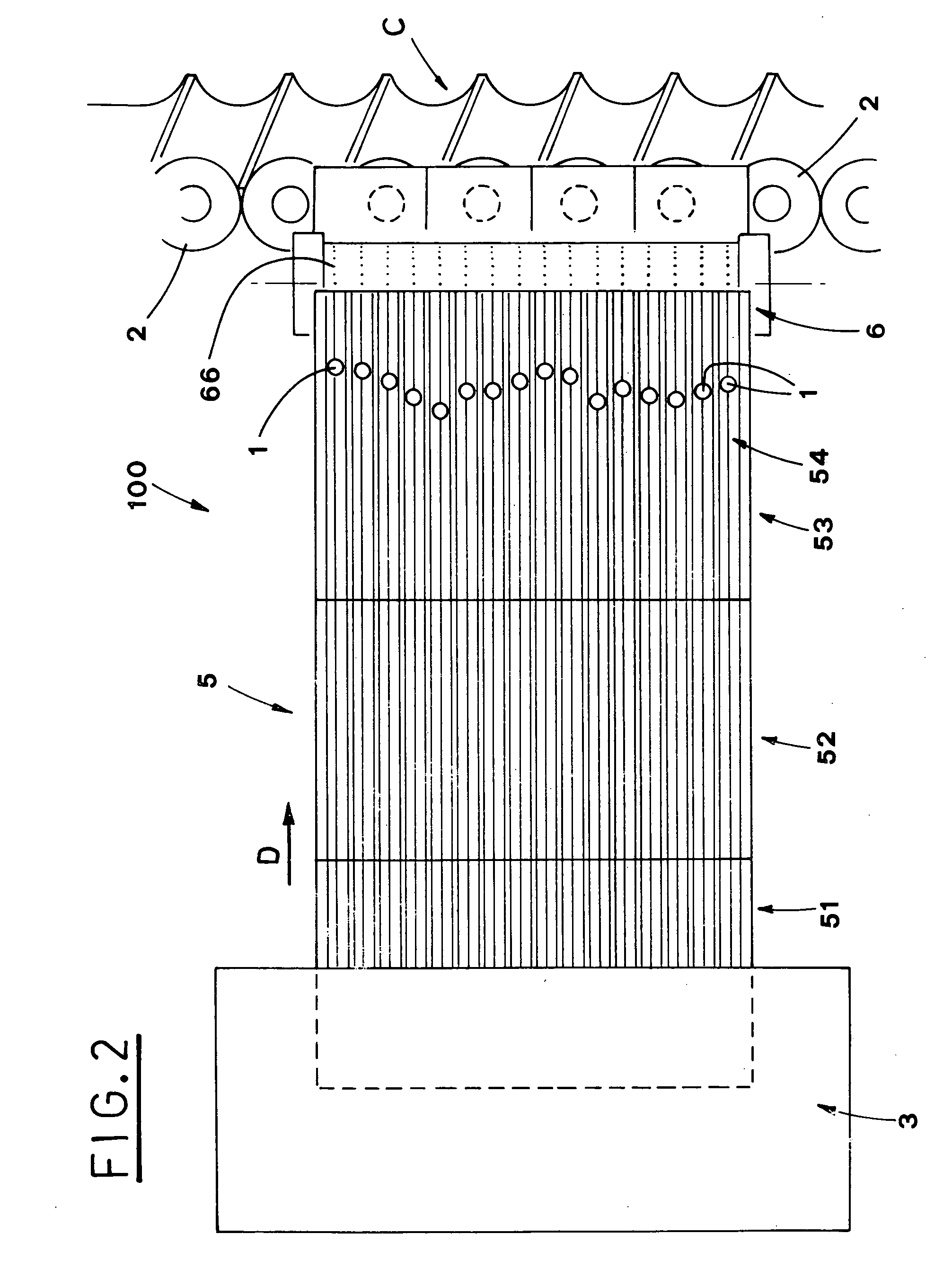
[0054] With reference to FIGS. 1 and 2, the reference indication M stands for a machine packaging pharmaceutical tablets 1 into corresponding bottles 2.

[0055] The tablets 1 are moved forward to a filling station R on a carrier 4 by a feed screw C operated discontinuously.

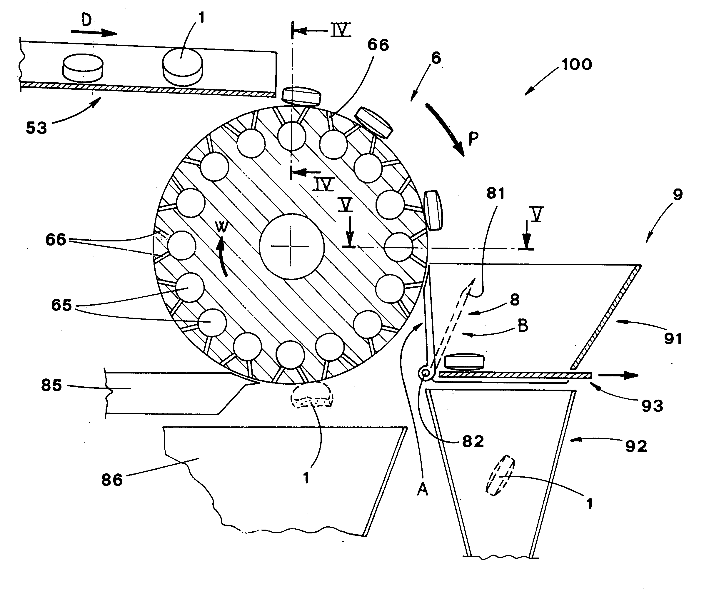
[0056] The reference numeral 100 indicates a unit for feeding and counting the tablets 1, which unit is an integral part of the packaging machine M.

[0057] According to what has been shown in FIG. 1, the unit 100 includes a feeding hopper 3, containing a mass of tablets 1 in bulk and equipped with a lower mouth 3a, through which the tablets 1 exit due to gravity force. The lower mouth 3a is provided with a relative closing shutter 3b.

[0058] In particular, according to a preferred embodiment, the hopper 3 is equipped with three outlet mouths 3a with relative shutters 3b, which move in such a way as to allow, when in use, to automatically adjust the outlet flow of the tablets 1, in order to regularly space them apa...


PUM


Abstract

A unit (100) for filling containers (2) with products (1), in particular pharmaceutical products (1), includes a hopper (3,3a) containing a mass of products (1) in bulk, conveying means (5,6) aimed at feeding the products (1) leaving the hopper (3) along a predetermined path (P) up to a station (SR), where the containers (2) are filled with the products (1). The containers (2) are fed to the filling station (SR) by transporting means (4,C). A checking station (SC) for checking the products (1) is situated along the path (P) upstream of the filling station (SR). The conveying means (5,6) include first means (51,52,53) consisting of vibrating planes and second conveying means (6). The second conveying means (6) are situated at the checking station (SC) between the conveying vibrating planes means (51,52,53) and the filling station (SR). The second conveying means (6) are equipped with holding means (65) for holding single products (1) thus forming, on the second conveying means (6), a series of single products (1), spaced apart and moving forward to the filling station (SR) along a portion of the path (P).

Description

FIELD OF THE INVENTION [0001] The present invention relates to automated packaging of small products into containers. [0002] In particular, the invention relates to a unit for continuously feeding and counting such products, mainly pharmaceutical products, such as tablets, pills or capsules for pharmaceutical use, from now on called simply pharmaceutical tablets without losing the universality, and for subsequently introducing the pharmaceutical tablets into bottles or the like. BACKGROUND OF THE INVENTION [0003] In the pharmaceutical production field, there are commonly known and used packaging machines for automatic packaging of pharmaceutical tablets supplied in bulk into bottles. [0004] Usually, a packaging machine of known type includes several working groups, among which, in particular, there are a device for orderly feeding and counting tablets, preferably performing a tablet quality check, and a device for filling the bottles, moving stepwise on a conveyor, with a predetermi...

Claims


Application Information

Patent Timeline
IPC IPC(8): G06M7/00B65B1/08B65B1/16B65B1/30B65B5/08B65B5/10B65B35/06B65B35/14B65B35/18B65B35/34B65B35/46B65B37/04B65B37/14B65B57/14B65B57/20B65B65/08B65G47/84
CPCB65B5/08B65B5/103B65B35/14B65B35/18B65B37/04Y10S53/90B65B57/14B65B57/20B65B65/08B65G47/848B65B37/14
Inventor CICOGNANI, SERGIO
Owner IMA IND MASCH AUTOMATICHE SPA
Why Eureka
Try Eureka