Compact counterflow heat exchanger

a heat exchanger and counterflow technology, applied in the field of heat exchangers, can solve the problems of weld splatter, distortion of thin sheet metal fins, and unreliable production of compact micro-channel heat exchangers b>10/b> using micro-channel flow passages

Inactive Publication Date: 2005-10-06
UNITED TECH CORP
View PDF0 Cites 56 Cited by
  • Summary
  • Abstract
  • Description
  • Claims
  • Application Information

AI Technical Summary

Benefits of technology

[0009] Another novel aspect of the present invention is a method of making a heat exchanger comprising the steps of preparing a substrate layer of multiple square metal tubes arranged adjacent and physically attached to each other in a horizontal plane, each tube having a longitudinally extending offset bend; configuring multiple layers in a vertical plane of multiple square metal tubes arranged adjacent to each other and the substrate layer in a horizontal plane and having interposed between each layer of multiple metal tubes physically and communicating therewith a braze alloy thus forming a heat exchange core; causing the braze alloy within the core to bond the multiple layers of multiple square metal tubes forming a core mass comprising in a vertical plane, multiple layers of multiple square metal tubes arranged adjacent and physically attached to each other and the substrate layer; forming in alternate tube layers counter-flow fluid channels communicating across the entire horizontal plane thereof; providing the core mass with side containment shells and manifolds in communication with the multiple square metal tube core mass and the counter-flow channels; and brazing the heat exchanger to bond parts thereof together

Problems solved by technology

However, a premium is placed on system mass for aerospace design because of the energy expense of achieving and maintaining flight.
Production of compact micro-channel heat exchangers 10 using micro-channel flow passages has yielded somewhat unreliable results because conventional fabrication methods cannot be controlled sufficiently well to yield consistent flow passage dimensions.
Alternatively, tack welding is used and welding of the many hundreds of fins is usually done by hand, which can be costly.
When the assembly of very small flow passage heat exchangers attempted however, distortion of the thin sheet-metal fins, weld splatter, arid braze drop-through often form significant and uncontrollable flow path obstructions.

Method used


Image

  • Compact counterflow heat exchanger
  • Compact counterflow heat exchanger
  • Compact counterflow heat exchanger

Examples


Embodiment Construction

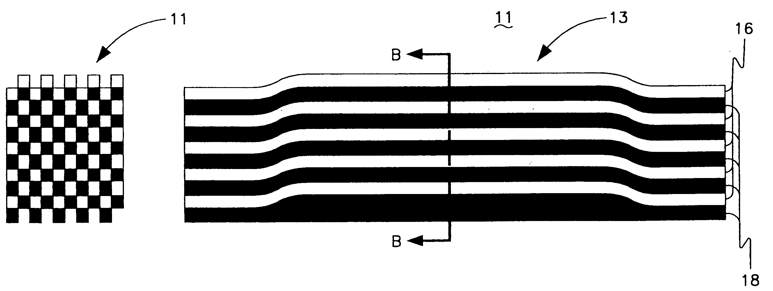
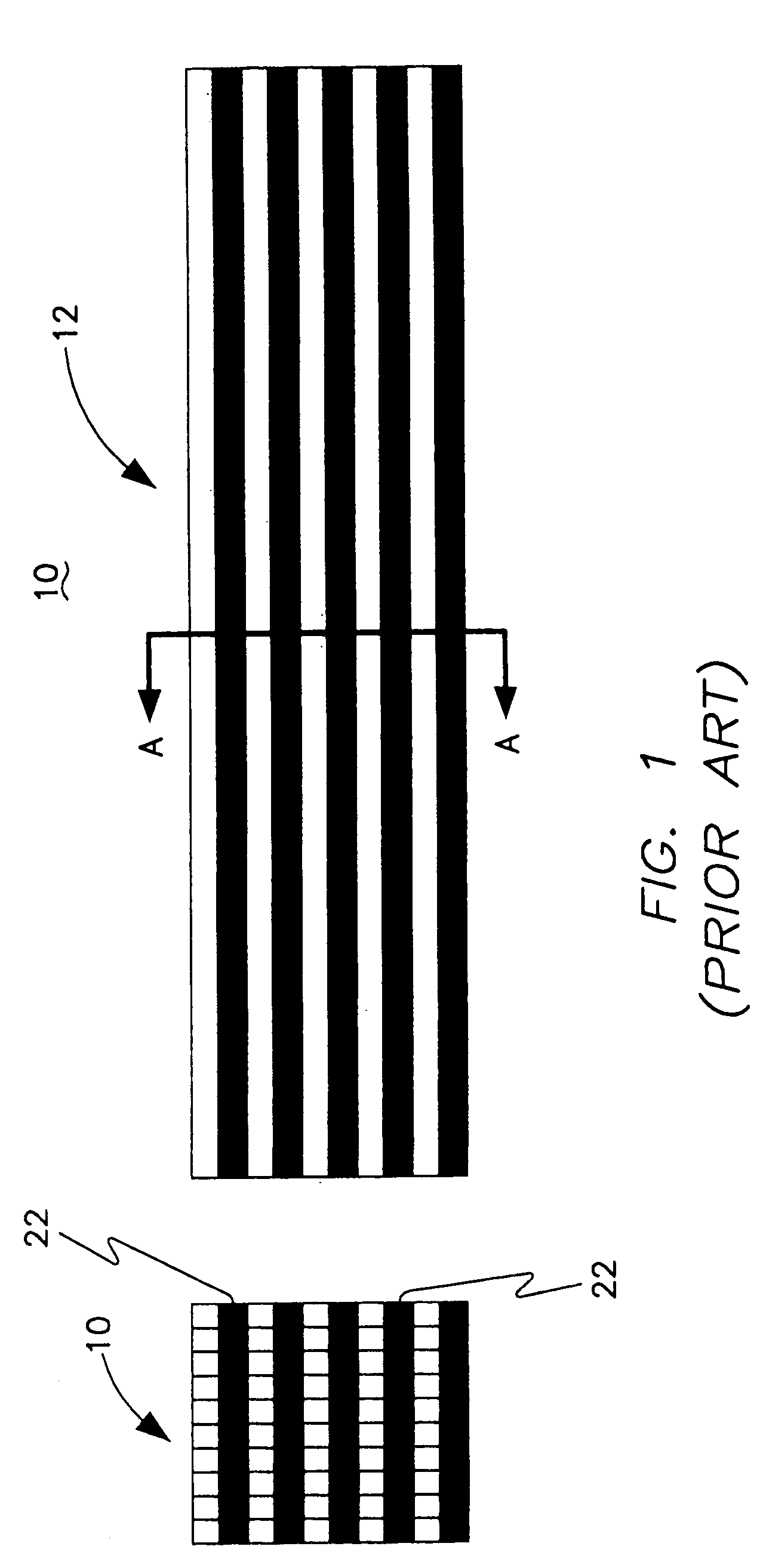
[0014]FIG. 1 shows a typical baseline heat transfer arrangement comprising a heat exchange core assembly 10 of square-formed seamless channels 16, and an identical square formed seamless counterflow channel 18. The channels 16, 18 each have multiple square tubes 12 of equal dimensions, 10 and arranged in parallel configuration.

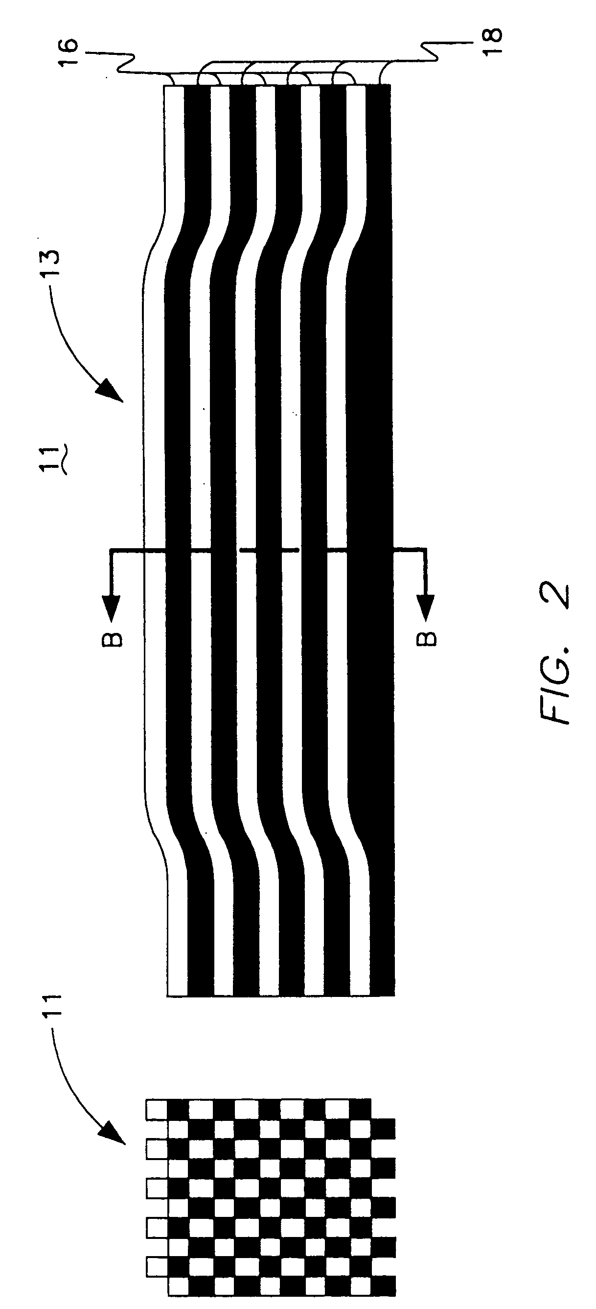
[0015] Onto the substrate layer 22 are added seriatim multiple layers of the tubes 12, each provided with a particular geometric feature. The tubes 12 are stacked in a vertical plane and arranged adjacent to each other and the substrate layer 22. In other words, tube 12 comprising the channel 16, 18 or the assembly 10 are arranged, or “stacked”, in ascending and descending column-like channels, both above and below one another, in an alternating checkerboard pattern, as shown in section A-A.

[0016] In preparing the core assembly 10, each one of the tubes 12 forming channels 16, 18 is made of a suitable material having desired heat transfer characteristics, su...


PUM


Abstract

A geometric arrangement of components in a compact counter-flow heat exchanger that allows for either an increase in effectiveness at a set mass, or a reduction in heat exchanger mass at a set effectiveness, or a combination of the two. The geometric arrangement can be achieved by either tube bending at the level of piece part manufacture and subsequent care during the tube stacking process, or by elastic deformation of the tube stack at the time of bonding.

Description

BACKGROUND OF THE INVENTION [0001] 1. Field of the Invention [0002] The present invention relates to heat exchangers, particularly, high-efficiency compact counter-flow heat exchangers. [0003] 2. Discussion of the Related Art [0004] In the art of heat exchangers, it is generally acknowledged that fin effectiveness takes on values between zero and one, as constrained by conservation of energy principles. More specifically, the value of the fin effectiveness is always less than one for common engineering materials because of their finite thermal diffusivity. [0005] However, a premium is placed on system mass for aerospace design because of the energy expense of achieving and maintaining flight. Under ordinary conditions, each flight system performs a variety of functions to successfully complete its mission. A common function necessary to aerospace system operation is the power conversion function. To the extent that a given power conversion function can be accomplished more effective...

Claims


Application Information

Patent Timeline
Patent Type & Authority Applications(United States)
IPC IPC(8): F28D7/00F28F7/00
CPCF28D7/0008F28F2009/0287
Inventor KUDIJA, CHARLES T. JR.
Owner UNITED TECH CORP
Why Eureka
Try Eureka