
Vibration-dampening drill collar

Inactive Publication Date: 2005-10-06
PHOENIX TECH SERVICES
View PDF12 Cites 46 Cited by
  • Summary
  • Abstract
  • Description
  • Claims
  • Application Information

AI Technical Summary

Benefits of technology

[0008] It is an object of the present invention, therefore, to provide a simple apparatus effective in dampening down-hole vibration in the tool-housing region of a drill string, even in rough or underbalanced drilling environments, while not requiring significant fluid flow for its utility.
[0013] This novel drill collar is especially useful in rough or underbalanced drilling applications, supporting and centralizing the sensor and enhancing measurement accuracy by dampening flow-based harmonic vibrations, absorbing vibration from lateral tool movement, and stabilizing / centralizing the sensor within the central aperture. Also, the novel drill collar allows the operator to run lower fluid rates while drilling, minimizing formation damage from fluid invasion.

Problems solved by technology

While such sensors provide highly useful information about the down-hole drilling environment, vibration due to the drilling process can damage the sensors.
An axial load is applied to the drill bit during drilling into underlying formations, and this produces vibrations in the overlying drill string, and vibration can occur due to drill string rotation in deviated or directional wellbores.
Also, drilling fluid flow around the tool can initiate harmonic vibrations and side-to-side “slapping” of the tool ensues.
However, existing means to dampen drill string vibrations or provide shock absorption suffer from numerous disadvantages, including high manufacturing cost, failures of inherently unreliable “point-contact” mechanical shock absorbers (such as belly springs), and the requirement for a significant drilling fluid throughflow to support certain stabilization devices (which can result in formation damage from fluid invasion).
Also, in rough or underbalanced drilling environments, conditions are such that excessive vibration can defeat currently known tool protection means.

Method used


Image

  • Vibration-dampening drill collar
  • Vibration-dampening drill collar
  • Vibration-dampening drill collar

Examples


Embodiment Construction

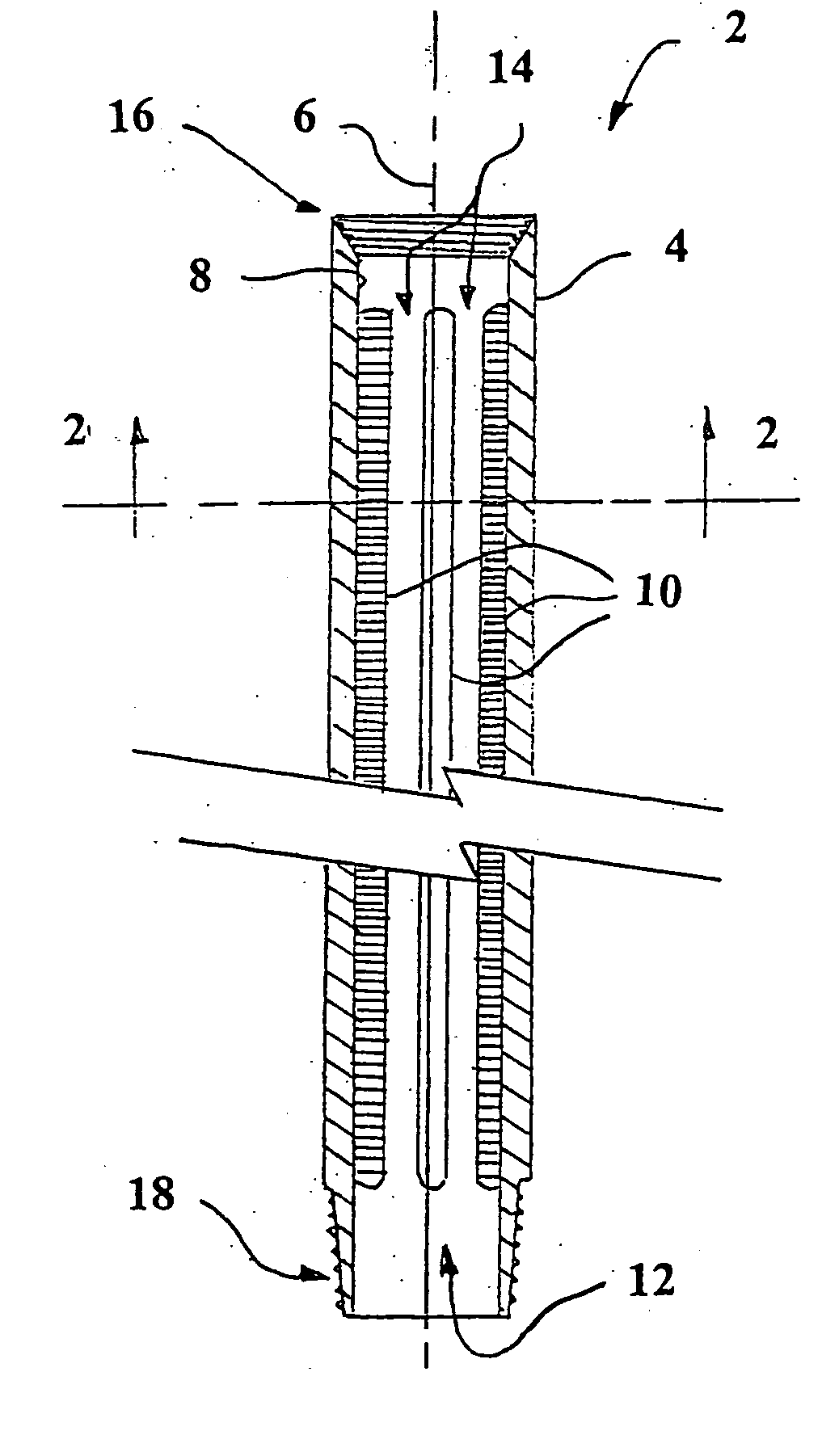
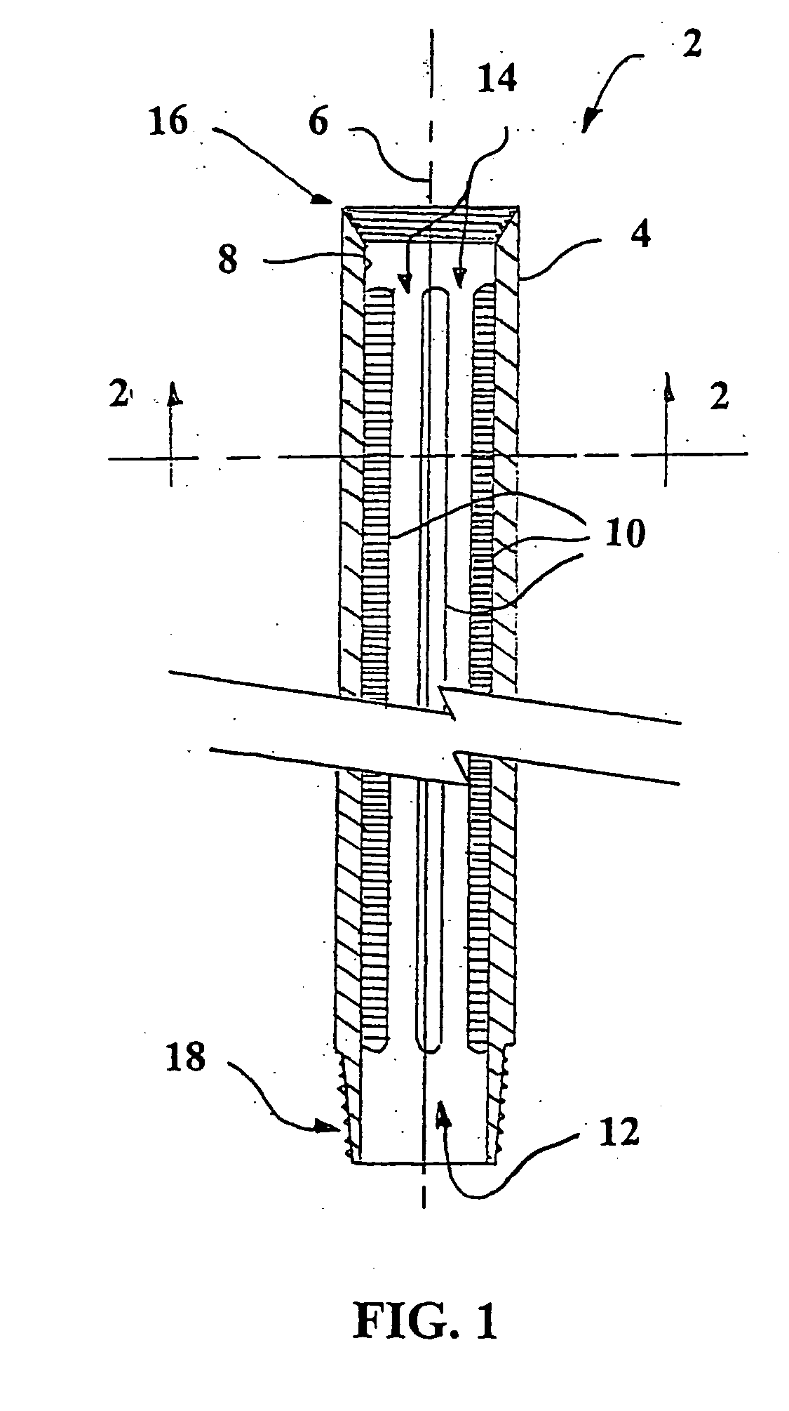
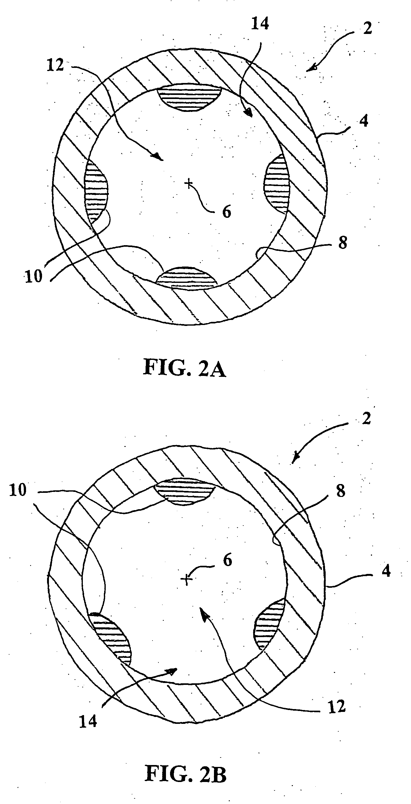
[0019] Referring now in detail to the accompanying drawings, there is illustrated an exemplary embodiment of a drill collar according to the present invention generally referred to by the reference numeral 2.

[0020] The exemplary drill collar 2 is for use with measurement-while-drilling and / or logging-while-drilling sensors (not shown) employing electro-magnetic transmission modes, the drill collar 2 comprising a hollow, cylindrical sleeve 4 having a longitudinal axis 6. The sleeve 4 has an inner surface 8 facing towards the longitudinal axis 6, and a box end 16 and pin end 18 at opposed ends of the sleeve 4 for connecting the drill collar 2 to adjacent string sections (not shown) (although double box end or double pin end connections may be used in some preferred embodiments). In this exemplary embodiment, the sleeve 4 is composed of a non-magnetic nickel alloy such as Monel™, although other non-magnetic materials may be suitable in various contexts. In exemplary embodiments, the d...


PUM


Abstract

A drill collar primarily for use with measurement-while-drilling and logging-while-drilling sensors, the drill collar composed of a non-magnetic nickel alloy, and having three or four elongate nitral elastomer ribs parallel the longitudinal axis and mounted on the inner surface of the drill collar, defining a central aperture for receiving the down-hole sensor and inter-rib apertures for receiving drilling fluid. This novel drill collar is especially useful in rough or underbalanced drilling applications, protecting the sensor and enhancing measurement accuracy by dampening flow-based harmonic vibrations, absorbing vibration from lateral tool movement, and stabilizing / centralizing the sensor within the central aperture. Also, the novel drill collar allows the operator to run lower fluid rates while drilling, minimizing formation damage from fluid invasion.

Description

FIELD OF THE INVENTION [0001] The present invention relates generally to apparatus for protecting down-hole tools such as sensors during drilling, and more particularly to apparatus for protecting down-hole sensors from the effects of vibration produced when drilling a well. BACKGROUND OF THE INVENTION [0002] In typical drilling systems utilized in the oil and gas industries, a rig is established at a desirable location, the rig comprising a rotatable drill string (consisting of drill pipe sections and heavier drill collars, the latter fitting around the lower drill pipe) and a drill bit at the down-hole end. During drilling, this rotatable component of the rig is rotated from the surface, causing the drill bit to cut into the downwardly adjacent rock formations, with the weight of the drill collar assisting in driving the drill bit downward into contact with the underlying rock. Drill collars also act as conduits for the drilling fluids used to lubricate the drill bit and carry cut...

Claims


Application Information

Patent Timeline
IPC IPC(8): E21B17/16E21B47/017
CPCE21B17/07E21B47/011E21B17/16E21B47/017
Inventor CLARK, BRENT ALEXANDER
Owner PHOENIX TECH SERVICES
Learn More