Attachment and liquid supplying

a liquid supply device and liquid supply technology, applied in printing, other printing apparatuses, etc., can solve the problems of increased running cost, ink cartridge replacement, limited ink capacity of ink cartridges,

Inactive Publication Date: 2005-10-06
SEIKO EPSON CORP
View PDF10 Cites 15 Cited by
  • Summary
  • Abstract
  • Description
  • Claims
  • Application Information

AI Technical Summary

Benefits of technology

[0010] In order to solve the above problems, an attachment of the present invention is mounted on a carriage so that the attachment can be replaced with a liquid container for containing liquid mounted on the carriage which includes a liquid jet head for jetting the liquid. The attachment supplies the liquid introduced from outside to the liquid jet head. In addition, the attachment is provided with a pressure control means in a flow passage where the liquid introduced from outside and disposed in the attachment body is supplied to the liquid jet head.
[0011] According to the present invention, the attachment is mounted on the carriage in place of the liquid container, so that liquid can be supplied to the liquid jet head from outside through the attachment. In addition, a pressure of liquid to be supplied to the liquid jet head from outside can be secured constantly by the pressure control means provided in the attachment. Accordingly, a liquid jet quality of the liquid jet head can be secured uniformly.
[0012] The attachment of the invention includes a first liquid supplying section, to which the liquid from outside is introduced, in the flow passage within the attachment body, a second liquid supplying section in which the liquid from the first liquid supplying section is flowed and through which the flowed liquid is supplied to the liquid jet head, and the pressure control means between the first liquid supplying section and the second liquid supplying section. The pressure control means is a valve device which causes the first liquid supplying section to communicate with the second liquid supplying section when a liquid pressure of the second liquid supplying section is equal to or lower than a predetermined reference pressure and also causes the first liquid supplying section not to communicate with the second liquid supplying section when a liquid pressure of the second liquid supplying section is higher than the predetermined reference pressure.
[0013] According to the present invention, if a liquid pressure in the side of the second liquid supplying section for supplying ink to the liquid jet head is equal to or lower than the predetermined reference pressure, the valve device cause the first liquid supplying section to communicate with the second liquid supplying section. The liquid of the first liquid supplying section flows in the second liquid supplying section to raise the liquid pressure of the second liquid supplying section. And, if the liquid pressure of the second liquid supplying section approaches the reference pressure, the valve device causes the first liquid supplying section not to communicate with the second supplying section. Accordingly, the liquid pressure of the second liquid supplying section is held near to the reference pressure. As a result, the weight of ink drops ejected from the liquid jet head is equally distributed so that a printing quality does not vary.
[0014] The attachment of the invention includes a first liquid supplying section, to which the liquid from outside is introduced, in the middle of the flow passage, a second liquid supplying section in which the liquid from the first liquid supplying section is flowed and through which the flowed liquid is supplied to the liquid jet head, and the pressure control means between the first liquid supplying section and the second liquid supplying section. The pressure control means is a valve device which causes the first liquid supplying section to communicate with the second liquid supplying section when the liquid differential pressure between the first liquid supplying section and the second liquid supplying section is equal to or higher than a predetermined reference pressure and also causes the first liquid supplying section not to communicate with the second liquid supplying section when the differential pressure is lower than the predetermined reference pressure.
[0015] According to the present invention, the valve device causes the first liquid supplying section to communicate with the second liquid supplying section when the differential pressure between the first liquid supplying section and the second liquid supplying section is equal to or higher than a reference pressure. The liquid of the first liquid supplying section flows in the second liquid supplying section to raise the liquid pressure of the second liquid supplying section. And, if the differential pressure is lower than the reference pressure, the valve device causes the first liquid supplying section not to communicate with the second liquid supplying section. Accordingly, the liquid pressure of the second liquid supplying section is held under a pressure which the liquid differential pressure between the second liquid supplying section and the first liquid supplying section is taken as a reference pressure. As a result, the weight of ink drops ejected from the liquid jet head is equally distributed so that a printing quality does not vary.

Problems solved by technology

However, ink capacity of the ink cartridge is limited in the on-carriage type of inkjet printing device.
Therefore, ink cartridges need to be replaced frequently and a running cost increases, when a relatively large amount of printing is performed.
Accordingly, there is a problem in that a printing quality is different according to the amount of ink remaining in the ink cartridge for supplying ink.
Therefore, a minute pressure variation or pressure pulse acts on the ink to be supplied to the printing cartridge, which makes it possible to reduce a printing quality.
Since the pump or the like needs to be mounted and controlled in an active system, the entire system becomes complicated.

Method used


Image

  • Attachment and liquid supplying
  • Attachment and liquid supplying
  • Attachment and liquid supplying

Examples


first embodiment

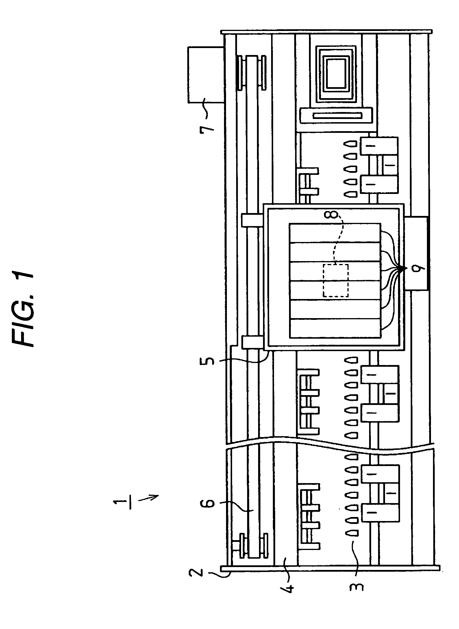
[0041] Hereinafter, a first embodiment of the present invention will be described with reference to FIGS. 1 to 9. FIG. 1 is a plan view of an inkjet-type recording device (hereinafter, referred to as a printer 1) as a liquid jet device of the present embodiment.

[0042] The printer 1 includes a frame 2 as shown in FIG. 1. Platens 3 are installed in the frame 2, on which papers are fed by a paper feeding mechanism (not shown). A guide member 4 is installed parallel to the platens 3 in the frame 2. A carriage 5 is inserted and supported movably in an axis direction of the guide member 4 thereon. Further, the carriage 5 is driven by and connected to a carriage motor 7 through a timing belt 6. Therefore, driving the carriage motor 7 makes the carriage 5 travel back and forth along the guide member 4.

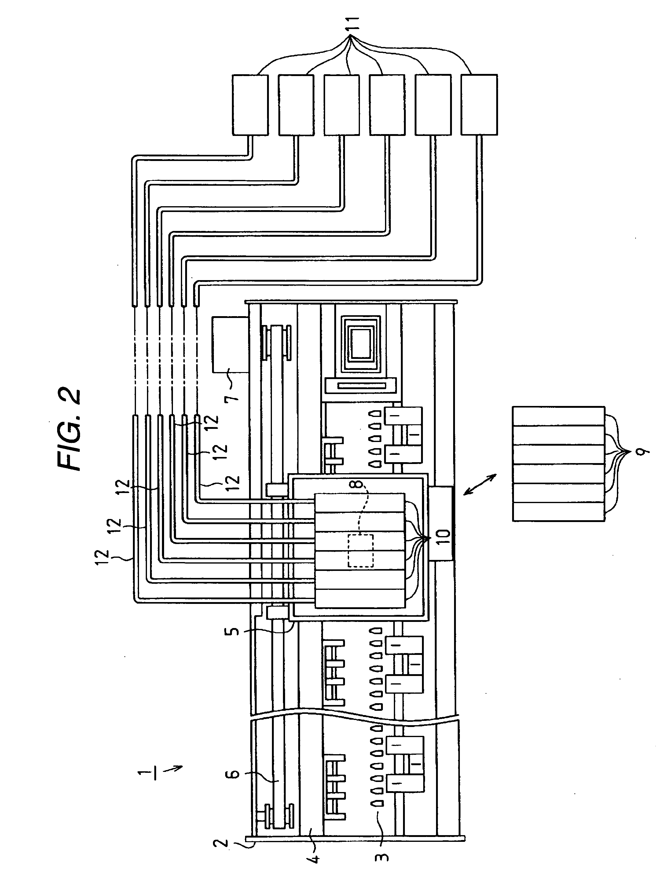
[0043] A print head 8 as a liquid jet head is mounted on a surface of the carriage 5 opposite to the platens 3. Six ink cartridges 9 as liquid containers are mounted on the carriage 5, which...

second embodiment

[0089] Next, the second embodiment of the present invention will be described with reference to FIG. 10. The present embodiment is characterized by a configuration which has the pressure control means (valve device) described in the first embodiment. Therefore, like reference numerals are used to denote identical elements of the first embodiment in the following embodiment and the detailed description of that will be omitted.

[0090]FIG. 10 is a cross-sectional view of essential parts of the attachment 10.

[0091] As shown in FIG. 10, a first concave portion 95 having a substantially cylindrical shape is formed in the one side 15a of the unit case 15, which communicates with the connection portion 17. A film member 97, which covers the first concave portion 95 is adhered to the one side 15a by heat welding. Accordingly, a substantially-cylindrical ink supply chamber 99 serving as a first liquid supplying section and a flow passage is defined by the first concave portion 95 and the fil...

third embodiment

[0104] Next, the third embodiment of the present invention will be described with reference to FIG. 11. Since the present embodiment is characterized by a configuration which has the pressure control means (valve device) described in the first embodiment and the second embodiment, like reference numerals are used to denote identical elements of the first embodiment and the second embodiment in the following embodiment and the detailed description of that will be omitted.

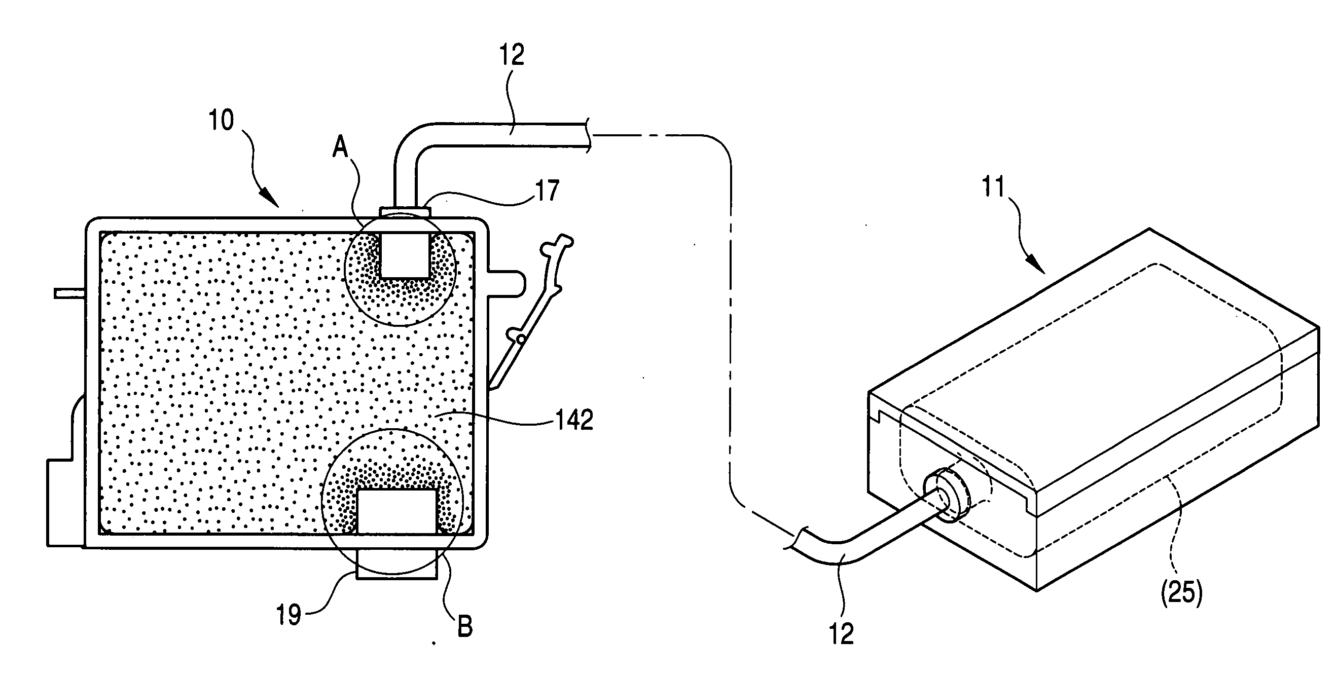
[0105]FIG. 11 is a partial cross-sectional view of an attachment 10.

[0106] As shown in FIG. 11, the unit case 15 of the attachment 10 includes an ink supply chamber 140 for containing ink therein, the ink of the outer ink tank 11 (not shown) is introduced from the connection portion 17 through the ink supply tube 12, and the ink is supplied to the print head 8 from the ink outlet portion 19.

[0107] A porous body 142 as a porous member is accommodated in the ink supply chamber 140. The porous body 142 temporarily ho...


PUM


Abstract

An attachment is mountable on a carriage in place of a liquid container that contains liquid and that is mounted on the carriage having a liquid jet head for jetting liquid, so that the attachment can supply liquid introduced from outside to the liquid jet head. The attachment has a pressure control means provided in a flow passage which is formed in an attachment body and through which the liquid introduced from the outside is supplied to the liquid jet head.

Description

BACKGROUND OF THE INVENTION [0001] The present invention relates to an attachment and a liquid supplying device. [0002] An inkjet printer is widely known as a liquid jet device for jetting liquid to a target through a liquid jet head. The inkjet printer is composed of a carriage and a print head mounted on the carriage. While the carriage moves toward a printing medium as a target, ink is ejected from a nozzle formed in the print head, so that printing is performed on the printing medium. [0003] Among these kinds of inkjet-type printing devices, one of them has such a configuration (so-called on-carriage type) that includes respective ink cartridges for supplying ink to a print head, which are mounted so as to be installed detachably on the carriage. However, ink capacity of the ink cartridge is limited in the on-carriage type of inkjet printing device. Therefore, ink cartridges need to be replaced frequently and a running cost increases, when a relatively large amount of printing i...

Claims


Application Information

Patent Timeline
Patent Type & Authority Applications(United States)
IPC IPC(8): B41J2/01B41J2/175B41J29/38
CPCB41J2/17523B41J2/175B41J2/17556B41J2/315
Inventor SEINO, TAKEONAKA, TAKAHIROSHINADA, SATOSHIKIMURA, HITOTOSHI
Owner SEIKO EPSON CORP
Why Eureka
Try Eureka