Eureka AIR delivers breakthrough ideas for toughest innovation challenges, trusted by R&D personnel around the world.

Liquid distribution

a technology of liquid distribution and expulsion gas, which is applied in the direction of liquid transfer devices, liquid handling, instruments, etc., can solve the problems of wine bottle degradation, costly replacement or refilling of tanks, and remaining non-inert gas degrading liquid remaining in containers, etc., to reduce the degradation of liquid, and increase the pressure of liquid

Inactive Publication Date: 2010-04-22
COOK MELVIN SEYMOUR
View PDF18 Cites 0 Cited by
  • Summary
  • Abstract
  • Description
  • Claims
  • Application Information

AI Technical Summary

Benefits of technology

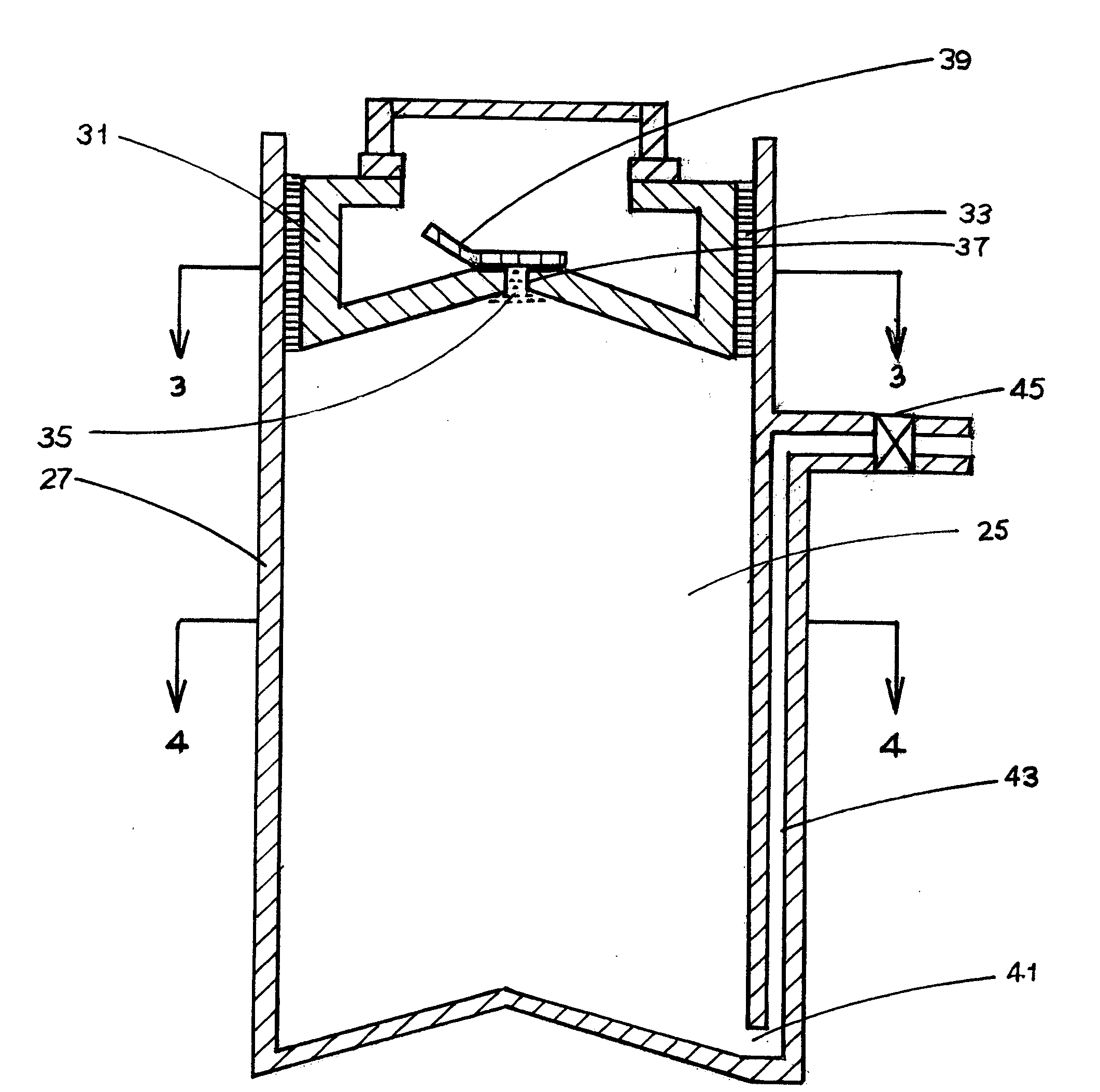
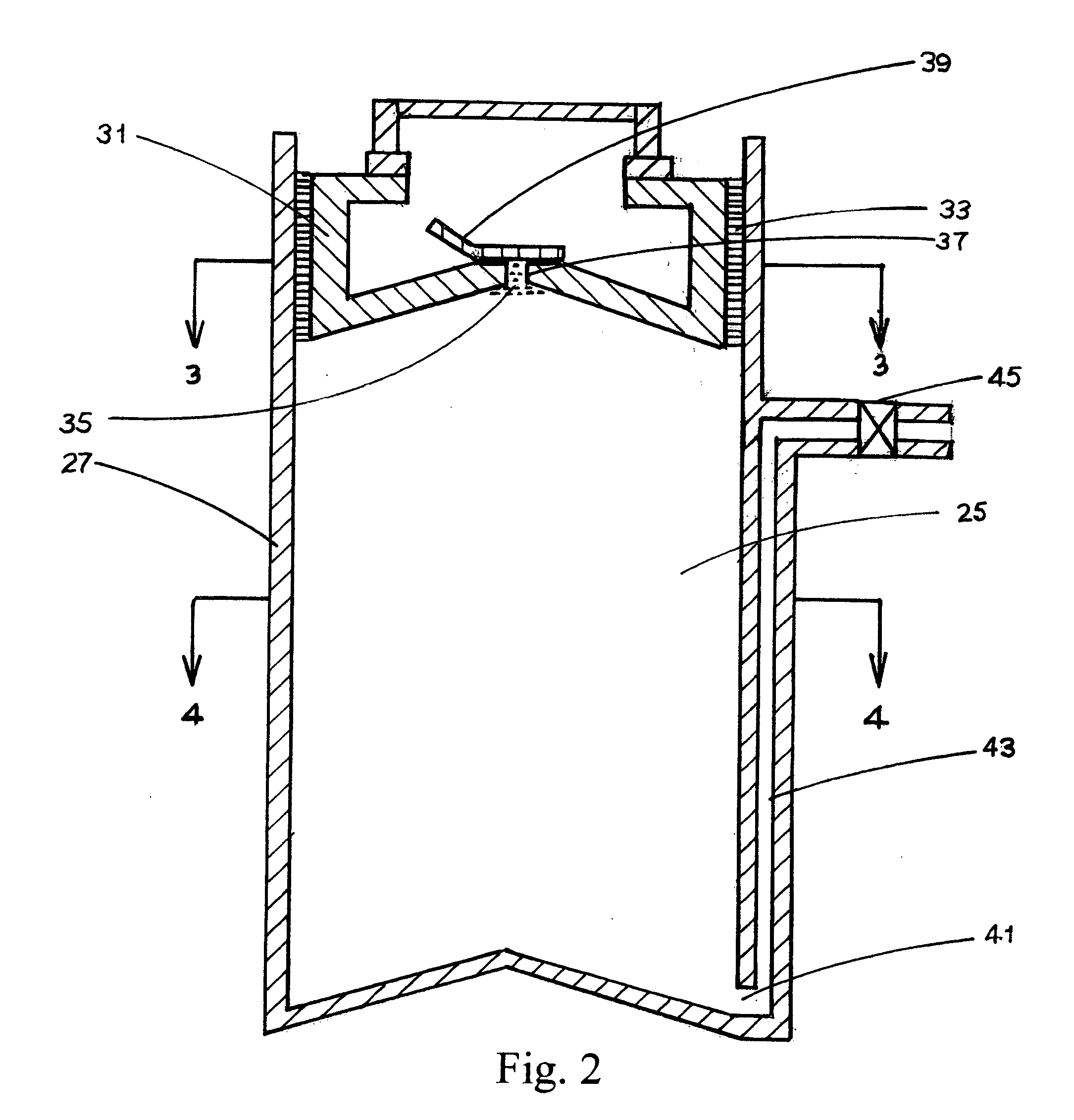
[0006]The object of the method disclosed is to minimize degradation of liquid in a container resulting from interaction with gas also present in the container. This is achieved by use of a piston on which an outlet is formed that is positioned in the container, said piston by its movement being able to increase the pressure of the liquid and the gas present in the container, said increase enabling the gas to be expelled from the container via the piston outlet and liquid to be distributed from the container via the piston outlet and / or another outlet from the container. Expelling the gas minimizes degradation of liquid in the container resulting from interaction with said gas.
[0007]In a preferred embodiment of the present invention, a piston on which an outlet is formed is positioned in a container holding liquid. The piston mounted in the container encloses the liquid and gas present in the container. The surface of the side of the facing the liquid is shaped so that any gas present in the container rises to the piston outlet. The container may have a cylindrical conformation with a circular cross-section and the piston may have a circular cross-section. The pressure of the liquid and that of any gas in the container is increased by movements of the piston that reduce the volume of the container in which the gas and liquid is held. This increase allows gas to be expelled from the container and liquid to be distributed from the container via the piston outlet.
[0009]If the piston is removed from the container, both it and the container can be cleaned and liquid placed in the container. Alternatively, liquid can be installed into the container via the piston outlet without removing the piston from the container. When the motions of the piston reduce the volume of the container in which the piston encloses the liquid and gas held in the container, those motions increase the pressure of said liquid and gas.

Problems solved by technology

For example, degradation of wine in a wine bottle can result from an interaction with air that entered the opened wine bottle.
However, it is a disadvantage of this particular prior art that all of the non-inert gas initially present in the container may not be expelled and any remaining non-inert gas may degrade liquid remaining in the container.
A further disadvantage of this prior art is that such tanks are costly and have to be replaced or refilled after some use.
However, while such a withdrawal reduces contamination of liquid remaining in the container due to interaction with gas remaining in the container, it does not completely remove all of the gas.
Thus, it does not completely eliminate degradation of liquid in the container.

Method used


Image

  • Liquid distribution
  • Liquid distribution
  • Liquid distribution

Examples


Embodiment Construction

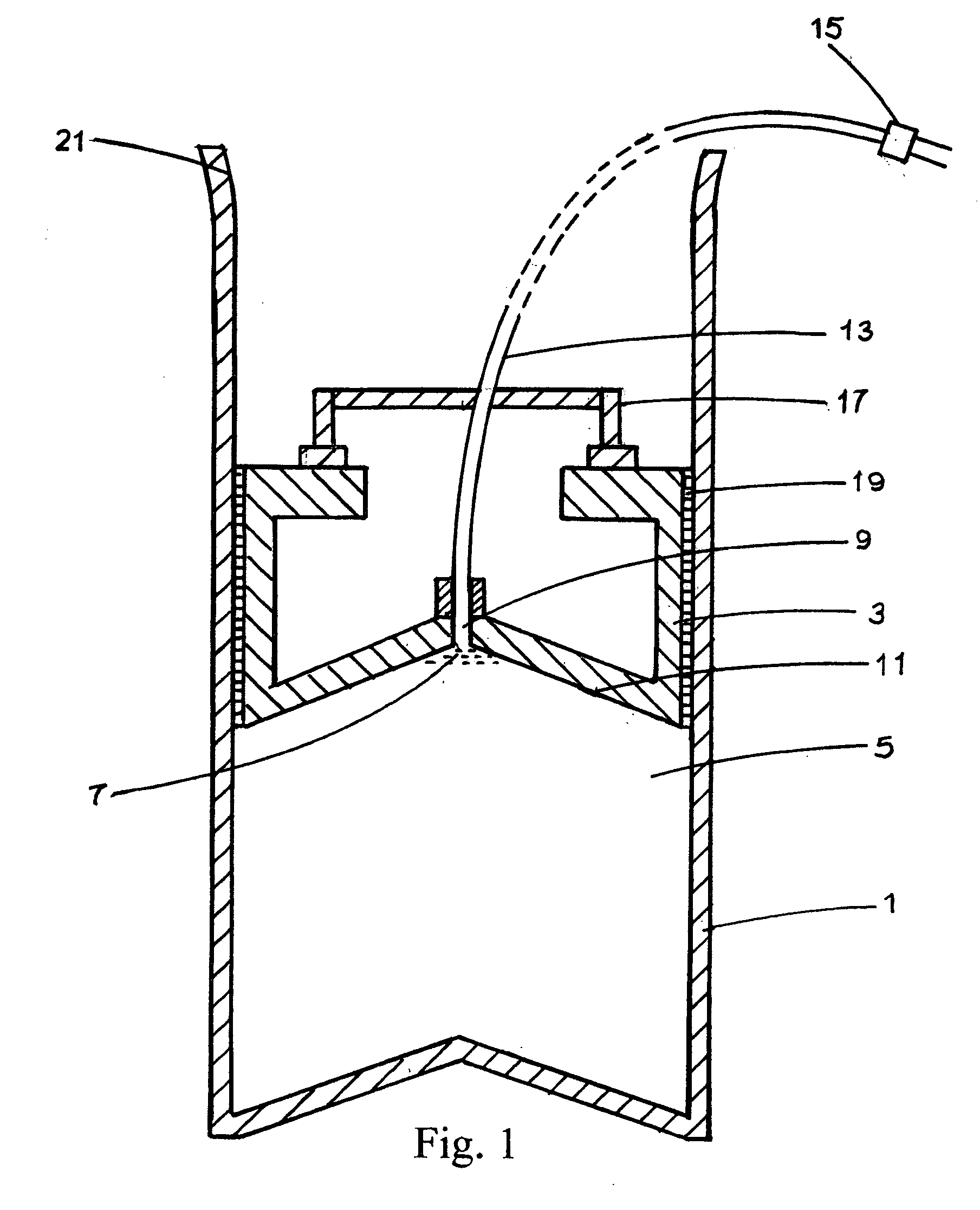
[0015]In FIG. 1, a section of a container 1 in which a movable piston 3 is mounted is shown. Liquid 5 is enclosed in the container by the piston and above the liquid, gas 7 is also enclosed in the container by the piston.

[0016]An outlet 9 is formed on the piston. The surface 11 of the piston facing the liquid is so shaped that any gas enclosed by the piston rises to the piston outlet. The piston outlet is connected via a piston outlet tube 13 to a piston outlet closure device 15. The piston outlet closure device can be, e.g., a plug, a clamp or a valve, and can be opened or shut. A handle 17 mounted on the piston can be used to move the piston. Preferably, the position of this handle can be adjusted to allow easier access to the piston outlet for the purpose of connecting a piston outlet tube to the piston outlet.

[0017]Material 19 is located on the portion of the piston surface adjacent to the container. This material prevents gas or liquid from leaving the container by moving aroun...


PUM


Abstract

A method for expelling gas and distributing liquid from a container is disclosed. A piston on which an outlet is formed is positioned in a container holding gas and liquid. The piston and cylinder are so formed that movements of the piston can increase the pressure of the gas and the liquid. This pressure increase can be used to expel gas from the container via the piston outlet and to distribute liquid from the container via the piston outlet and / or another outlet. Expelling the gas minimizes degradation of liquid remaining in the container due to an interaction with the gas.

Description

TECHNICAL FIELD[0001]The invention disclosed is a method for expelling gas and distributing liquid from a container by using a piston on which an outlet is formed. Expelling the gas minimizes degradation of liquid remaining in the container resulting from interaction with said gas.BACKGROUND OF THE INVENTION[0002]In certain cases, liquid in a container would be degraded by interaction with gas also present in the container. For example, degradation of wine in a wine bottle can result from an interaction with air that entered the opened wine bottle. In such cases, it is desirable to expel the gas from the container in order to minimize negative effects of such an interaction on liquid remaining in the container.[0003]In an example of the prior art, a tank containing an inert gas, e.g., argon, under pressure is used to blow said inert gas into a container holding liquid and non-inert gas. When this inert gas enters the container, it expels some of the non-inert gas. However, it is a d...

Claims


Application Information

Patent Timeline
Patent Type & Authority Applications(United States)
IPC IPC(8): B67D5/00
CPCB67D1/0885C12H1/16B67D1/102
Inventor COOK, MELVIN SEYMOUR
Owner COOK MELVIN SEYMOUR
Why Eureka
Eureka Blog
Learn More