Method and system for cooling a motor during motor startup

a technology of compressor motor and startup sequence, which is applied in the direction of mechanical equipment, refrigeration components, light and heating equipment, etc., can solve the problems of complex systems and increase costs, and achieve the effect of increasing the pressure of liquid coolan

Inactive Publication Date: 2021-08-12
CARRIER CORP
View PDF0 Cites 0 Cited by
  • Summary
  • Abstract
  • Description
  • Claims
  • Application Information

AI Technical Summary

Benefits of technology

[0021]In another example of the above described exemplary method for operating a heating ventilation and air conditioning (HVAC) system driving the liquid coolant comprises providing liquid coolant from the condenser to a reservoir and heating the liquid coolant in the reservoir, thereby increasing a pressure of the liquid coolant.

Problems solved by technology

Traditional air cooling of such systems can be inadequate for a high speed motor, and independent oil based liquid cooling leads to complex systems and increases costs.

Method used


Image

  • Method and system for cooling a motor during motor startup
  • Method and system for cooling a motor during motor startup
  • Method and system for cooling a motor during motor startup

Examples


Embodiment Construction

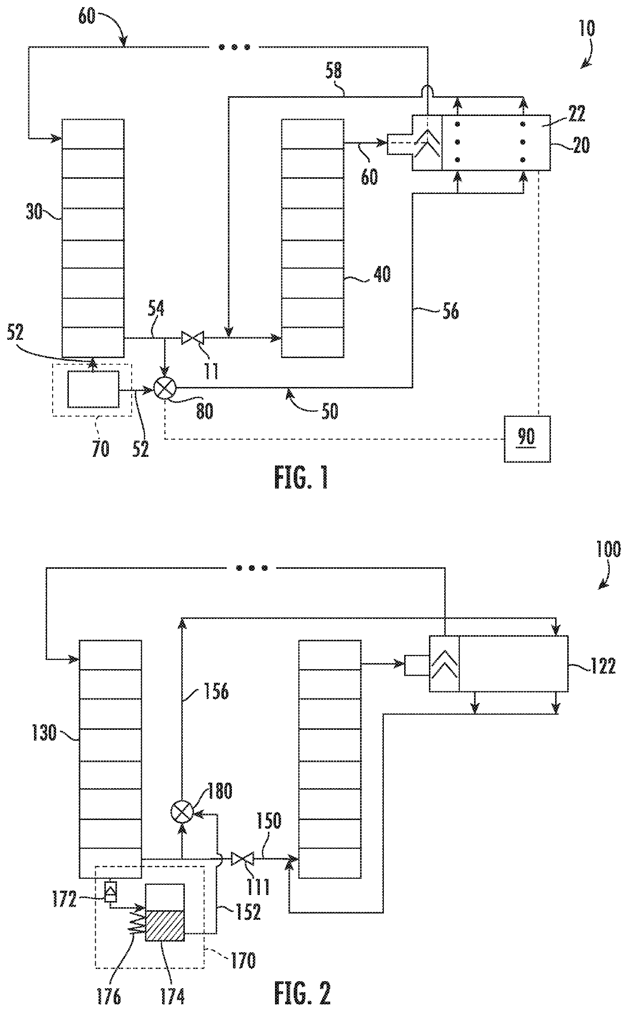
[0031]FIG. 1 schematically illustrates a vapor compression system with a compressor motor cooling subsystem 10 for a compressor 20 driven by a high speed motor 22 for HVAC applications. In one non-limiting example, the high speed motor 20 is a motor for a mini-centrifugal compressor. The system includes a condenser 30, an evaporator 40, and an expansion device 11 in fluid communication with the compressor 20. In order to provide cooling and lubrication to a high speed motor 22, a pressure rise generated by the compressor 20 provides liquid coolant from the condenser 30 to the motor 22 along a fluid flowpath 50 during full speed operations of the compressor 20. In the embodiment of FIG. 1, the liquid coolant cools and lubricates the motor 22, and is then provided to the evaporator 40 via the flowpath 58. Once in the evaporator 40, the coolant is evaporated, and provided to the compressor 20 in a vapor form along a vapor flowpath 60. The vapor flowpath 60 provides the evaporated coola...


PUM


Abstract

A HVAC system includes a compressor having a low pressure input and a high pressure output. The compressor is driven by a motor having a liquid coolant flowpath configured to cool and lubricate the motor. The motor has a coolant input and a coolant output. An evaporator is in communication with the compressor, and includes a coolant input and a coolant output. A condenser is in fluid communication with the evaporator and the compressor. A first coolant flowpath, includes a coolant drive system connecting the output of the condenser to a valve switching device. A second coolant flowpath connects the output of the condenser to the input of the evaporator and to a second input of the valve switching device. A third coolant flowpath connects the valve switching device to the inputs of the motor. A fourth coolant flowpath connects outputs of the motor to the input of the evaporator.

Description

TECHNICAL FIELD[0001]The present disclosure relates generally to compressor motor cooling and lubrication, and more specifically to compressor motor cooling and lubrication during a startup sequence.CROSS-REFERENCE TO RELATED APPLICATION[0002]This application claims priority to U.S. Provisional Patent Application No. 62 / 740,476 filed on Oct. 3, 2018.BACKGROUND[0003]Global warming and other environmental concerns have lead the heating, ventilation and cooling (HVAC) industry to explore alternative low Global Warming Potential (GWP) refrigerants in place of existing refrigerants in HVAC systems. However, due to their low pressure characteristics, some low GWP refrigerants, especially those suitable for use in small capacity systems such as rooftops and residential systems, require the utilization of a high-efficiency compressor, evaporator and condenser.[0004]Certain high-efficiency compressors, such as high speed centrifugal compressors, require a high speed motor for proper operatio...

Claims


Application Information

Patent Timeline
Patent Type & Authority Applications(United States)
IPC IPC(8): F25B1/053F25B31/00F25B31/02F25B41/20F25B49/02F25B9/00
CPCF25B1/053F25B31/008F25B31/026F25B41/20F25B49/022F25B31/002F25B9/002F25B2500/16F25B2500/26F25B2600/23F25B49/025F25B31/004F25B49/02
Inventor WANG, JINLIANGMAHMOUD, AHMAD M.COGSWELL, FREDERICK J.VERMA, PARMESH
Owner CARRIER CORP
Why Eureka
Try Eureka