Method and apparatus for correcting a defective pixel

Inactive Publication Date: 2005-10-06
CANON KK
View PDF7 Cites 82 Cited by
  • Summary
  • Abstract
  • Description
  • Claims
  • Application Information

AI Technical Summary

Benefits of technology

[0015] According to the present invention, an edge direction is detected in a highly reliable fashion, and, based on the de

Problems solved by technology

Some pixels do not have sufficiently high sensitivity due to a failure or degradation that can occur during or after the process of producing image sensors.
Such defective pixels do not output a correct signal corresponding to the intensity of incident light, and thus a white or black dot, which is not included in a subject, appears in an image.
However, the increase in the number of pixels causes an increase in probability that an image sensor has a defective pixel, despite advances in production techniques of image sensors.
However, storing information indicating locations of a large number of defective pixels in an expensive nonvolatile memory results in an increase in total cost.
This can cause a problem that, for example, when edges of an image intersect each other

Method used


Image

  • Method and apparatus for correcting a defective pixel
  • Method and apparatus for correcting a defective pixel
  • Method and apparatus for correcting a defective pixel

Examples


Example

First Embodiment

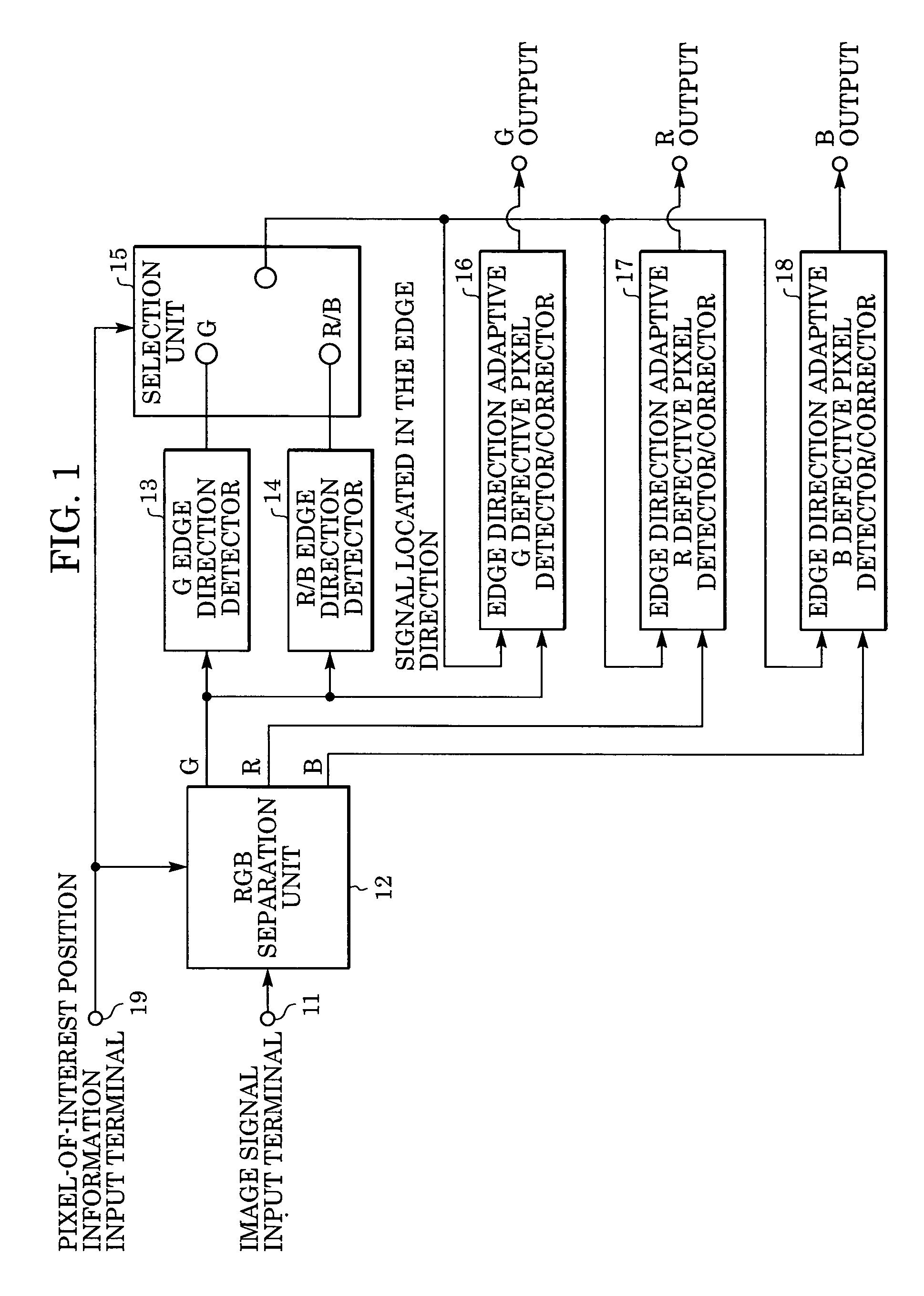
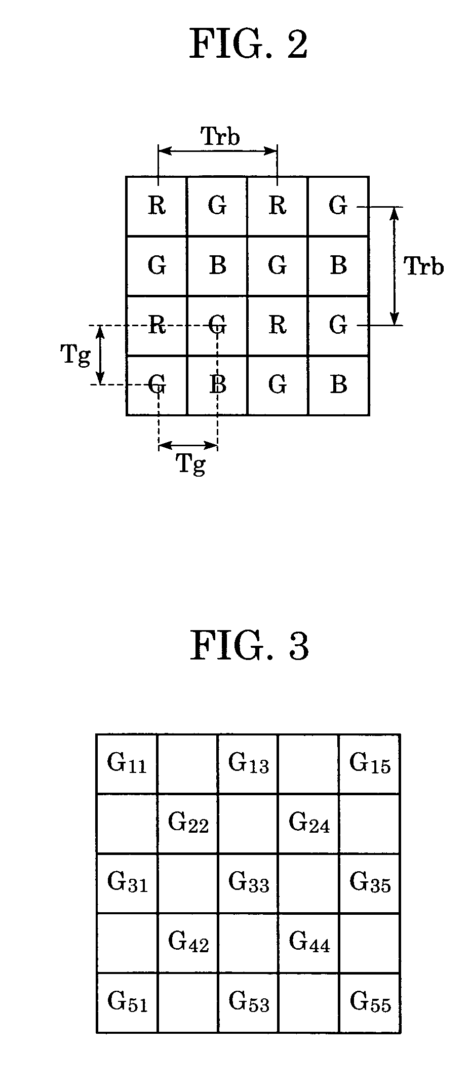
[0048]FIG. 1 is a schematic block diagram showing an image processing apparatus capable of correcting a defective pixel according to a first embodiment of the present invention. In this first embodiment, the present invention is applied to a single-plate image sensor with a primary-color Bayer array.

[0049] In FIG. 1, reference numeral 11 denotes an image signal input terminal for receiving an image signal output from an image sensor (not shown). Reference numeral 12 is an RGB separation unit that separates image signal input into color components corresponding to respective color filters.

[0050] Reference numeral 13 denotes a G edge direction detector for generating a signal located in the edge direction for use in detection and correction of a defective pixel of pixels at locations at which a G (green) filter is disposed. Reference numeral 14 denotes an R / B edge direction detector for generating a signal located in the edge direction for use in detection and corre...

Example

Second Embodiment

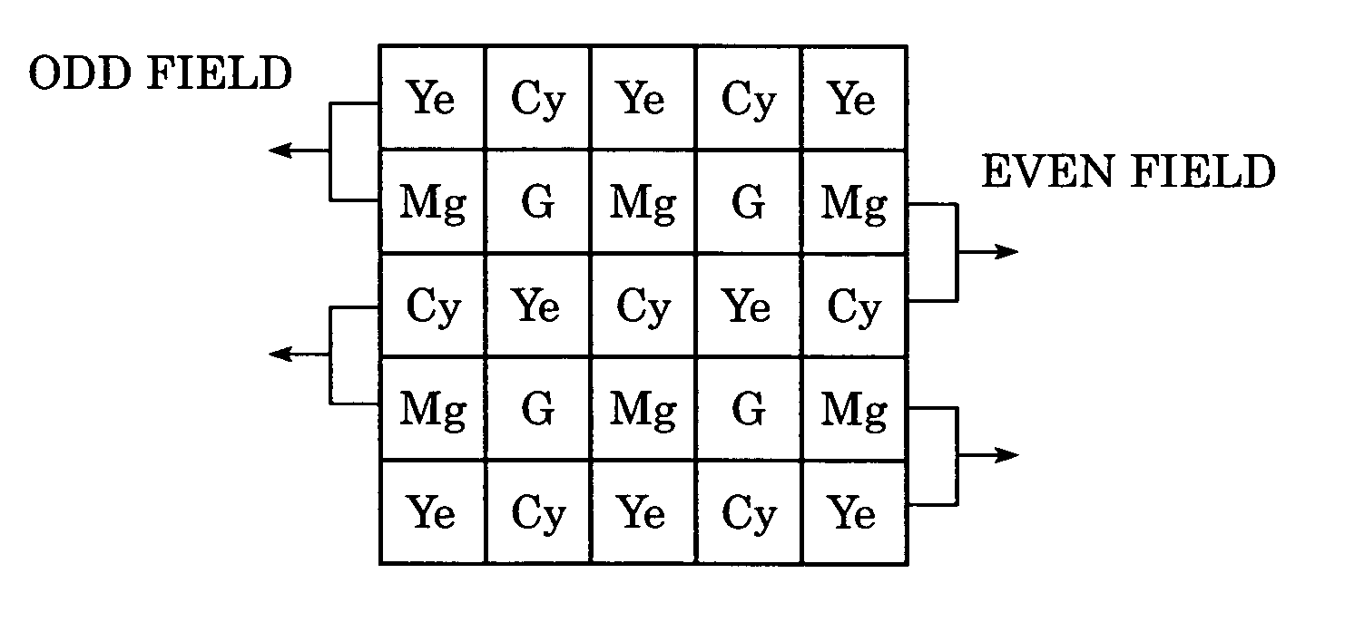
[0118]FIG. 11 is a schematic block diagram showing an image processing apparatus capable of correcting a defective pixel according to a second embodiment of the present invention. In this second embodiment, the invention is applied to a single-plate field-integration image sensor with a complementary color array.

[0119] In FIG. 11, reference numeral 141 denotes an image signal input terminal. An image signal to be subjected to the defective pixel detection / correction process is output from an image sensor (not shown) and input via this image signal input terminal 141. Reference numeral 143 denotes a color carrier removing unit for removing a color carrier component superimposed on the input image signal for each pixel. Reference numeral 144 denotes an edge direction detector for detecting an edge direction at a pixel of interest, from a luminance component obtained by removing the color carrier from the image signal.

[0120] Reference numeral 145 denotes a defective...

Example

Third Embodiment

[0143] The aspects of the present invention may also be achieved by supplying a software program code implementing the functions of any of the embodiments described above to a computer connected to a plurality of devices or to a computer in a system whereby the computer (a CPU or an MPU) in the system or the apparatus controls various devices in accordance with the program code.

[0144] Furthermore, the program code may be stored in a memory provided on an expansion board inserted into the computer or an expansion unit connected to the computer, and a part or all of the process may be executed by a CPU or the like provided on the expansion board or the expansion unit thereby realizing the functions according to the invention. Storage media which can be employed, but not limited to, in the present invention to store the program code include a floppy disk, hard disk, optical disk, magneto-optical disk, CD-ROM, magnetic tape, non-volatile memory card, and ROM.

[0145] Fu...


PUM


Abstract

An image processing apparatus and method for detecting and correcting a defective pixel in an image output from an image sensor including a plurality of pixels, comprising detection of an edge direction based on the image data, detection of a defective pixel included in the image sensor based on the detected edge direction, and correction of the selected defective pixel.

Description

BACKGROUND OF THE INVENTION [0001] 1. Field of the Invention [0002] The present invention relates to a technique of correcting a defective pixel of an image sensor. [0003] 2. Description of the Related Art [0004] In image sensors such as CCDs, pixels are produced in the form of a two-dimensional array by using semiconductor technology. Some pixels do not have sufficiently high sensitivity due to a failure or degradation that can occur during or after the process of producing image sensors. Such defective pixels do not output a correct signal corresponding to the intensity of incident light, and thus a white or black dot, which is not included in a subject, appears in an image. [0005] It is known to detect defective pixels included in an image sensor and store information associated with defective pixels in a nonvolatile memory during the process of producing the image sensor in a factory such that degradation in image quality due to defective pixels can be compensated for based on t...

Claims


Application Information

Patent Timeline
IPC IPC(8): H04N3/14H04N5/363H04N5/367H04N5/372H04N5/378H04N9/04H04N9/083H04N9/64
CPCH04N9/045H04N5/3675H04N25/683H04N25/70H04N23/84H04N25/136H04N25/134
Inventor TAJIMA, KAORINOBUOKA, KOSUKE
Owner CANON KK
Why Eureka
Try Eureka