Optical image measuring apparatus

a measuring apparatus and optical image technology, applied in the field of optical image measuring apparatus, can solve the problems of difficult shortening the measurement time in view of measurement fundamentals, difficult to use the apparatus in fields that require high-resolution images, and time-consuming 105

Inactive Publication Date: 2005-10-06
KK TOPCON
View PDF19 Cites 52 Cited by
  • Summary
  • Abstract
  • Description
  • Claims
  • Application Information

AI Technical Summary

Benefits of technology

[0028] Note that in the present invention, the term “synchronous” in the phrase “(modulation) frequency synchronous with a shift amount of the frequency” implies that the (modulation) frequency is (substantially) equivalent to the shift amount, that the (modulation) frequency is n times larger than the shift amount, and that the (modulation) frequency is 1 / n of the shift amount (where n is an integer of 2 or more).
[0029] In addition, the term “different” in the phrase “whose frequencies are different depending on the depth region” implies none of the conditions that the frequency corresponding to a given depth region is equal to, n times higher than, and 1 / n of the frequencies corresponding to the other depth regions. Similarly, the term “different” in the phrase “shift the frequencies by different amounts” implies none of the conditions that the shift amount of a given frequency is equal to, n times larger than, nor 1 / n of the shift amounts of the other frequencies.

Problems solved by technology

Therefore, the measurement of the object to be measured 105 can be time consuming.
In addition, it is hard to shorten a measurement time in view of measurement fundamentals.
Therefore, it is likely to be hard to actually use the apparatus in fields that require a high-resolution image, such as a medical field and an industrial field.
Hence, in the case of taking images of the object to be measured in plural depth regions, it is necessary to scan the object to be measured for each depth region for measurement, so the measurement takes much time to complete.

Method used


Image

  • Optical image measuring apparatus
  • Optical image measuring apparatus
  • Optical image measuring apparatus

Examples


Embodiment Construction

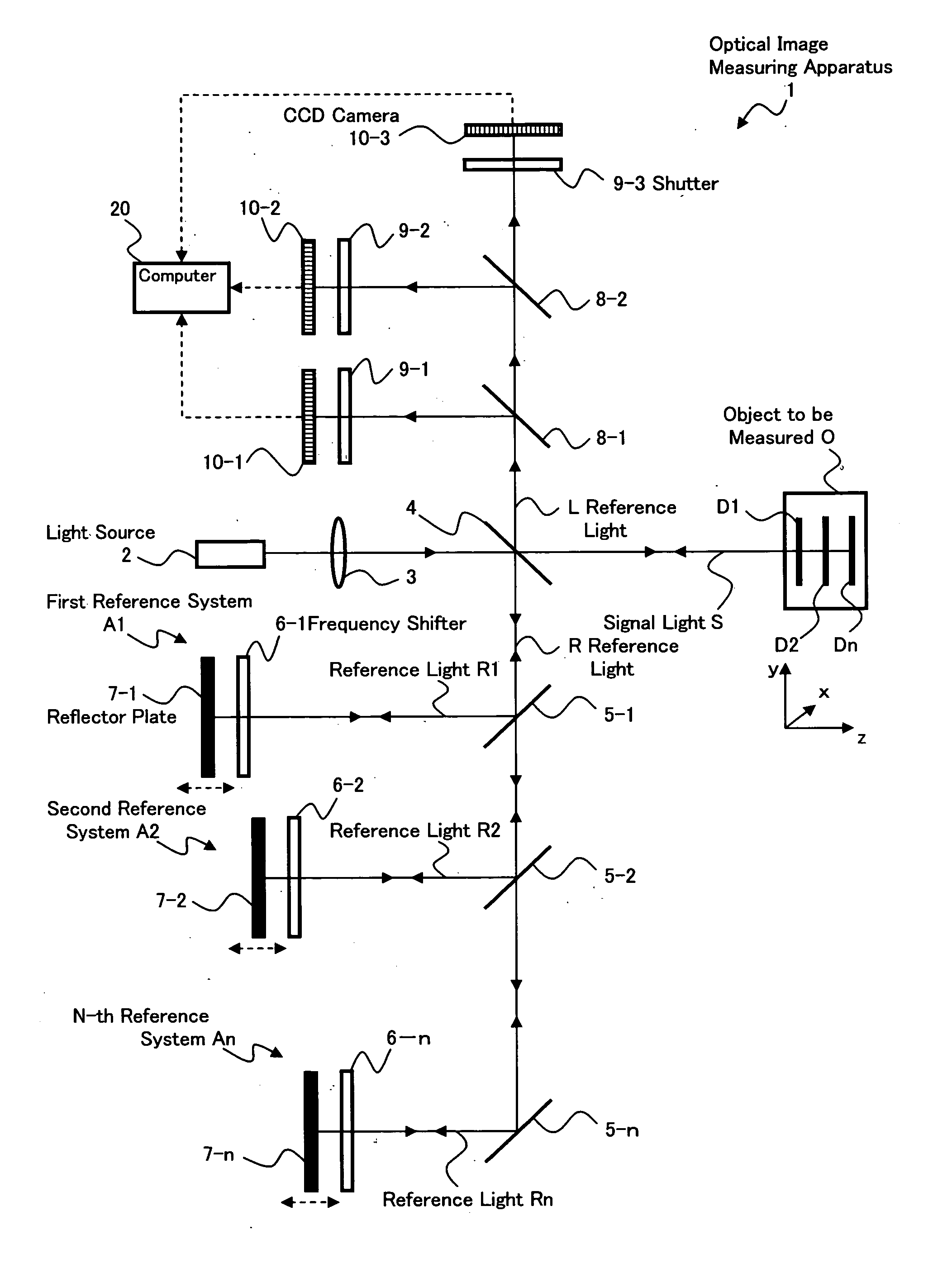
[0039] Hereinafter, an example of an optical image measuring apparatus according to an embodiment of the present invention will be described in detail with reference to the accompanying drawings.

(Structure of Apparatus)

[0040]FIG. 1 shows a schematic structure of an optical image measuring apparatus 1 according to a preferred embodiment of the present invention. The optical image measuring apparatus 1 is an apparatus usable in, for example, the medical and industrial fields, and has a structure for taking two-dimensional sectional images of an object to be measured O (hereinafter, referred to as “measuring object”), that is made of a scattering medium, in respective depth regions in parallel. Here, the depth region of the measuring object O means a region of the measuring object O at a given depth (depth position) (given z-coordinate in a three-dimensional coordinate system shown in FIG. 1). To be specific, the regions in question refer to regions defined by an area extending in a...


PUM

PropertyMeasurementUnit
coherent lengthaaaaaaaaaa
optical image measuringaaaaaaaaaa

Abstract

Provided is an optical image measuring apparatus capable of taking images of an object to be measured in plural depth regions in parallel. An optical image measuring apparatus of the present invention includes: a beam splitter (4) for dividing a light beam into signal light (S) and reference light (R); beam splitters (5-1 to 5-(n−1)) for dividing the reference light (R) into plural reference light beams (R1 to Rn); frequency shifters (6-1 to 6-n) for shifting frequencies of the reference light beams (R-1 to Rn) by different amounts; and reflector plates (7-1 to 7-n) arranged at different distances from an object to be measured (O). The reference light beams (R1 to Rn) and the signal light (S) reflected by the object to be measured in depth regions (D1 to Dn) are superimposed on each other to thereby produce interference light (L). Shutters (9-1 to 9-3) extract interference light components (L1 to Ln) from the reference light (L), and CCD cameras (10-1 to 10-3) receive the interference light component and convert the interference light component into electrical signals to output the signals. A computer (20) forms images in depth regions corresponding to the interference light components based on the electrical signals.

Description

BACKGROUND OF THE INVENTION [0001] 1. Field of the Invention [0002] The present invention relates to an optical image measuring apparatus employing a structure in which an object to be measured which is particularly a light scattering medium is irradiated with a light beam and a surface form or inner form of the object to be measured is measured based on a reflected light beam or a transmitted light beam to produce an image of a measured form. More particularly, the present invention relates to an optical image measuring apparatus for measuring the surface form or inner form of the object to be measured by using an optical heterodyne detection method to produce the image of the measured form. [0003] 2. Description of the Related Art [0004] In recent years, attention has been given to optical imaging techniques for producing an image of a surface or inner portion of an object to be measured using a laser light source or the like. In contrast to the conventional X-ray CT technique, op...

Claims


Application Information

Patent Timeline
Patent Type & Authority Applications(United States)
IPC IPC(8): G01B11/00A61B3/12A61B5/00G01B9/02G01N21/17G01N21/47
CPCA61B3/102A61B3/1225A61B5/0066A61B5/0073G01B2290/45G01B9/02012G01B9/02007G01B9/02003G01B9/02091G01B9/02028
Inventor CHAN, KINPUIAKIBA, MASAHIROFUKUMA, YASUFUMIOTSUKA, HIROYUKITSUKADA, HISASHI
Owner KK TOPCON
Why Eureka
Try Eureka