Magnetic recording media, method of manufacturing the same and magnetic recording apparatus

a technology of magnetic recording media and magnetic recording apparatus, which is applied in the direction of digital recording, maintaining head carrier alignment, instruments, etc., can solve the problems of low throughput, high possibility of adverse effects on data recorded on adjacent tracks, and difficulty in processing magnetic film into such a microstructure by photolithography

Inactive Publication Date: 2005-10-06
KK TOSHIBA
View PDF2 Cites 54 Cited by
  • Summary
  • Abstract
  • Description
  • Claims
  • Application Information

AI Technical Summary

Problems solved by technology

Magnetic recording media with a high recording density have such a problem that, when data are recorded on a track with a magnetic head, data recorded on the adjacent tracks may be adversely affected with a high possibility.
Incidentally, when a size of the magnetic marks is reduced to about 500 nm or less, it is difficult to process the magnetic film into such a microstructure by photolithography.
However, the electron beam lithography results in a low throughput because of slow drawing speed.
However, when the magnetic recording media is manufactured by using the imprint lithography method, the thickness of the magnetic film may be made unevenly, depending on the pattern in the servo regions.
As a result of this, it has become a problem that read and write of the magnetic data may be made unstable.

Method used


Image

  • Magnetic recording media, method of manufacturing the same and magnetic recording apparatus
  • Magnetic recording media, method of manufacturing the same and magnetic recording apparatus
  • Magnetic recording media, method of manufacturing the same and magnetic recording apparatus

Examples


first embodiment

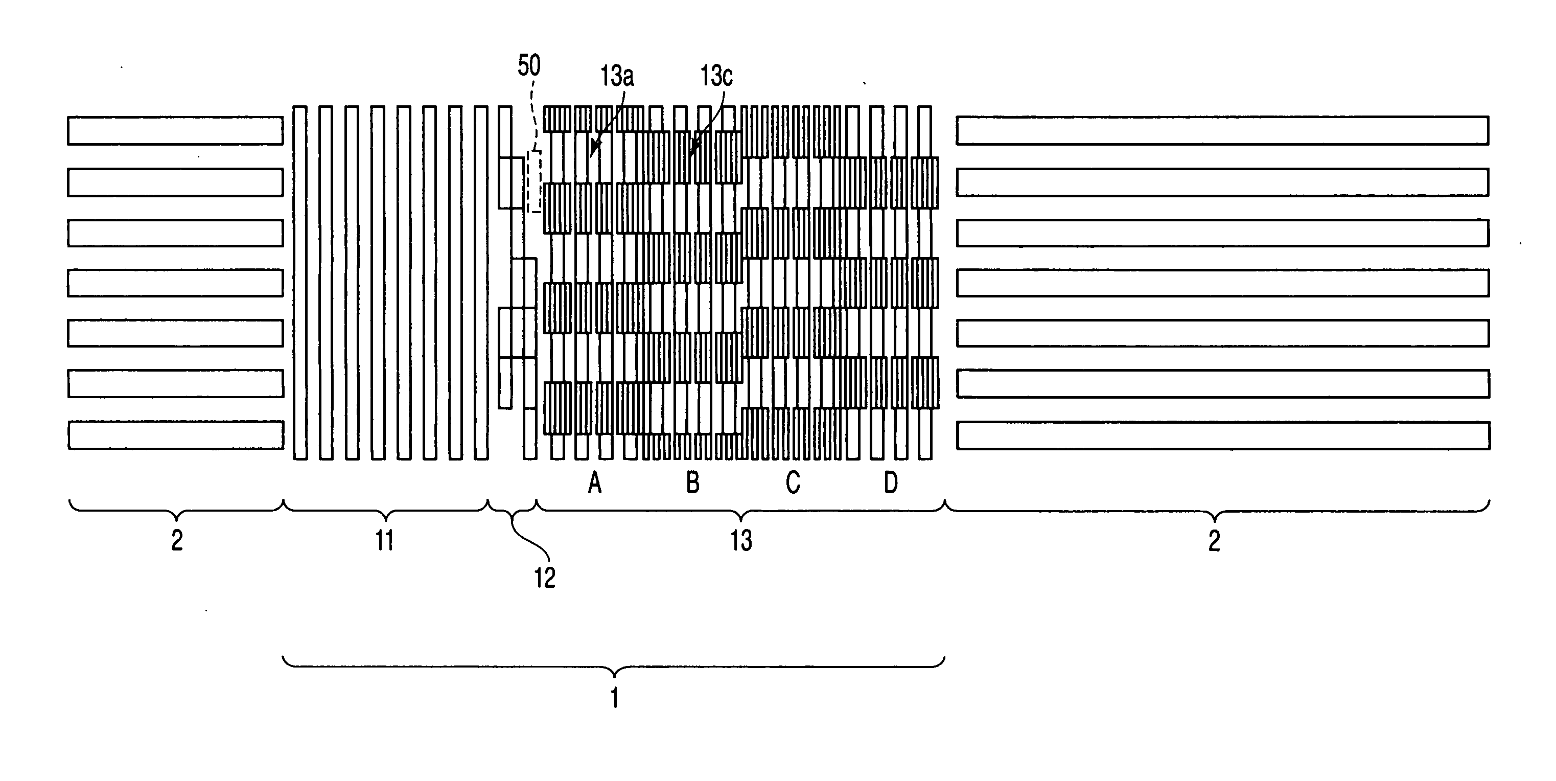
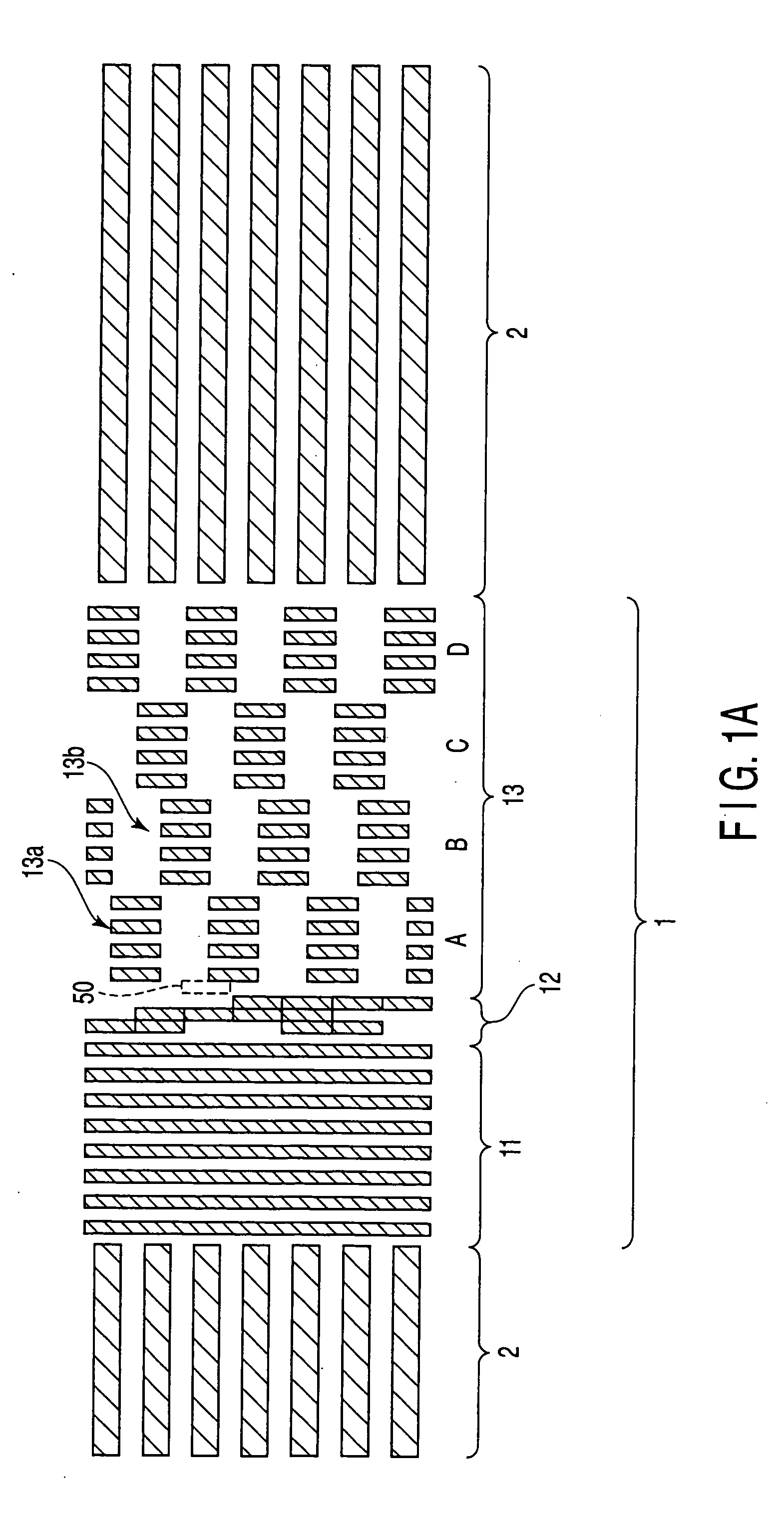
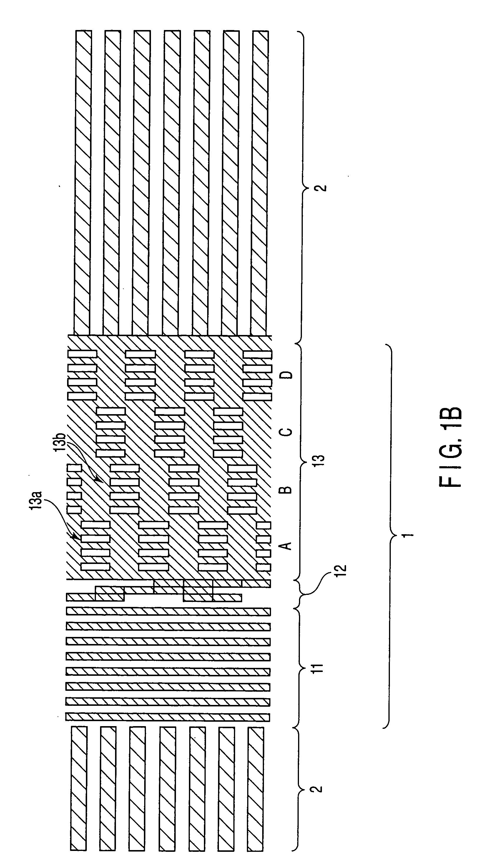
[0046]FIG. 4 is a plan view of the magnetic recording media according to this embodiment. As shown in this figure, the magnetic recording media includes the servo region 1 in which marks of a magnetic film are formed, and the data region 2 in which discrete tracks of the magnetic film are formed. The servo region 1 includes the preamble region 11, the address region 12 and the burst region 13.

[0047] In the preamble region 11, linear magnetic marks and spaces filled with the non-magnetic film between the marks are formed with the same intervals in the track direction. With this arrangement, the area ratio of the magnetic marks in the preamble region 11 is about 50%. In the address region 12, the pattern of the magnetic marks varies depending on the value of the address. Accordingly, the area ratio of the magnetic marks varies depending on the address. The area ratio of the magnetic discrete track in the data region 2 is set to about 67%. These regions are the same as those shown in ...

second embodiment

[0052]FIG. 5 is a plan view of a burst region of the magnetic recording media in this embodiment. The non-signal section 13c in the burst region 13 shown in FIG. 5 includes a plurality of linear marks of the magnetic film, in-plane geometry of which is a stripe parallel to the track direction. The rest of the structure is similar to that shown in FIG. 4. It should be noted that the pitch in the track width direction of the linear marks (second marks) formed in the non-signal section 13c shown in FIG. 5 is not particularly limited. In this embodiment, the width of each linear magnetic mark and the width of each non-magnetic space between the linear marks are set to a ratio of 3 to 1. Thus, the area ratio of the magnetic marks in the non-signal section 13c is about 75%. Consequently, the area ratio of the magnetic marks in the burst region 13 becomes about 63%.

[0053] In the magnetic recording media shown in FIG. 5, the area ratios of the magnetic marks are: about 50% for the preamble...

third embodiment

[0054]FIG. 6 is a plan view of a burst region of the magnetic recording media in this embodiment. The non-signal section 13c in the burst region 13 shown in FIG. 6 includes a plurality of dot marks of the magnetic film, in-plane geometry of which is a dot, formed in a periodic pattern. The pitch of the dot magnetic marks (second marks) in the non-signal section 13c is different from the pitch of the rectangular magnetic marks (first marks) in the signal section 13a. The rest of the structure is similar to that shown in FIG. 4. It should be noted that the pitch in the track width direction of the dot marks formed in the non-signal section 13c shown in FIG. 6 is not particularly limited. In this embodiment, the width of each dot magnetic mark and the width of each non-magnetic space between the dot marks are set to a ratio of 3 to 1 in the track direction and a ratio of 3 to 1 in the track width direction. Thus, the area ratio of the magnetic marks in the non-signal section 13c is abo...


PUM

PropertyMeasurementUnit
sizeaaaaaaaaaa
magneticaaaaaaaaaa
area ratioaaaaaaaaaa

Abstract

A magnetic recording media includes a servo region including a preamble region and a burst region and having marks of a magnetic film, and a data region having discrete tracks of the magnetic film. The burst region includes a signal section and a non-signal section, the signal section including rectangular marks of the magnetic film, in-plane geometry of which is a rectangle, formed in a periodic pattern in a track direction, and the non-signal section including marks of the magnetic film having a pattern different from the pattern of the rectangular marks in the signal section.

Description

CROSS-REFERENCE TO RELATED APPLICATIONS [0001] This application is based upon and claims the benefit of priority from prior Japanese Patent Application No. 2004-108107, filed Mar. 31, 2004, the entire contents of which are incorporated herein by reference. BACKGROUND OF THE INVENTION [0002] 1. Field of the Invention [0003] The present invention relates to a magnetic recording media, a method of manufacturing the recording media using imprint lithography, and a magnetic recording apparatus that uses the magnetic recording media. [0004] 2. Description of the Related Art [0005] As demands for higher capacity of magnetic recording apparatuses, magnetic recording media are required to increase a recording density. Magnetic recording media with a high recording density have such a problem that, when data are recorded on a track with a magnetic head, data recorded on the adjacent tracks may be adversely affected with a high possibility. In order to solve the problem, there has been propose...

Claims


Application Information

Patent Timeline
Patent Type & Authority Applications(United States)
IPC IPC(8): G11B5/65G11B5/012G11B5/596G11B5/82G11B5/84G11B5/855G11B5/86G11B20/12G11B27/30
CPCG11B5/59633G11B5/865G11B5/855
Inventor SAKURAI, MASATOSHIASAKURA, MAKOTOOKINO, TAKESHI
Owner KK TOSHIBA
Why Eureka
Try Eureka