Light panel illuminated by light emitting diodes

a technology light panels, which is applied in the field of lighting fixtures illuminated by a plurality of light emitting diodes, can solve the problems of large consumption of power, large heat generation, and relatively inefficient and fragile, and achieves high brightness, convenient reflection and dispersion, and suitable opacity.

Inactive Publication Date: 2005-10-06
SCHEXNAIDER CRAIG J
View PDF16 Cites 151 Cited by
  • Summary
  • Abstract
  • Description
  • Claims
  • Application Information

AI Technical Summary

Benefits of technology

[0031] The above noted objects and other objects of the invention are accomplished by a flat planar light fixture formed of a translucent panel with suitable opacity for the transmission of light that is illuminated by a plurality of high brightness LEDs disposed along the edges thereof. A layer of reflective material on a back surface of the panel facilitates reflection and dispersion of light that occurs within the panel through a front surface thereof. The LEDs are powered by low-voltage dire

Problems solved by technology

Incandescent illumination systems have significant disadvantages since they consume a lot of power and produce a great deal of heat, are relatively inefficient and fragile, and require frequent replacement.
Systems using fluorescent light sources also have several disadvantages since they require complicated circuitry including a ballast reactor (a coil of wire wrapped around a heavy iron core), and require substantial space for the location of the fluorescent lamps and circuit

Method used


Image

  • Light panel illuminated by light emitting diodes
  • Light panel illuminated by light emitting diodes
  • Light panel illuminated by light emitting diodes

Examples


Embodiment Construction

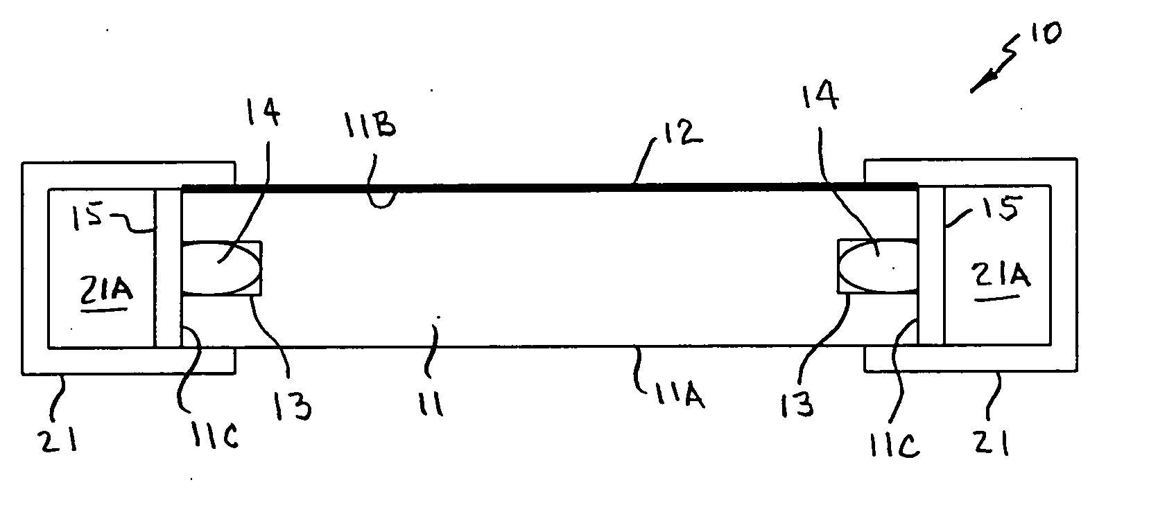
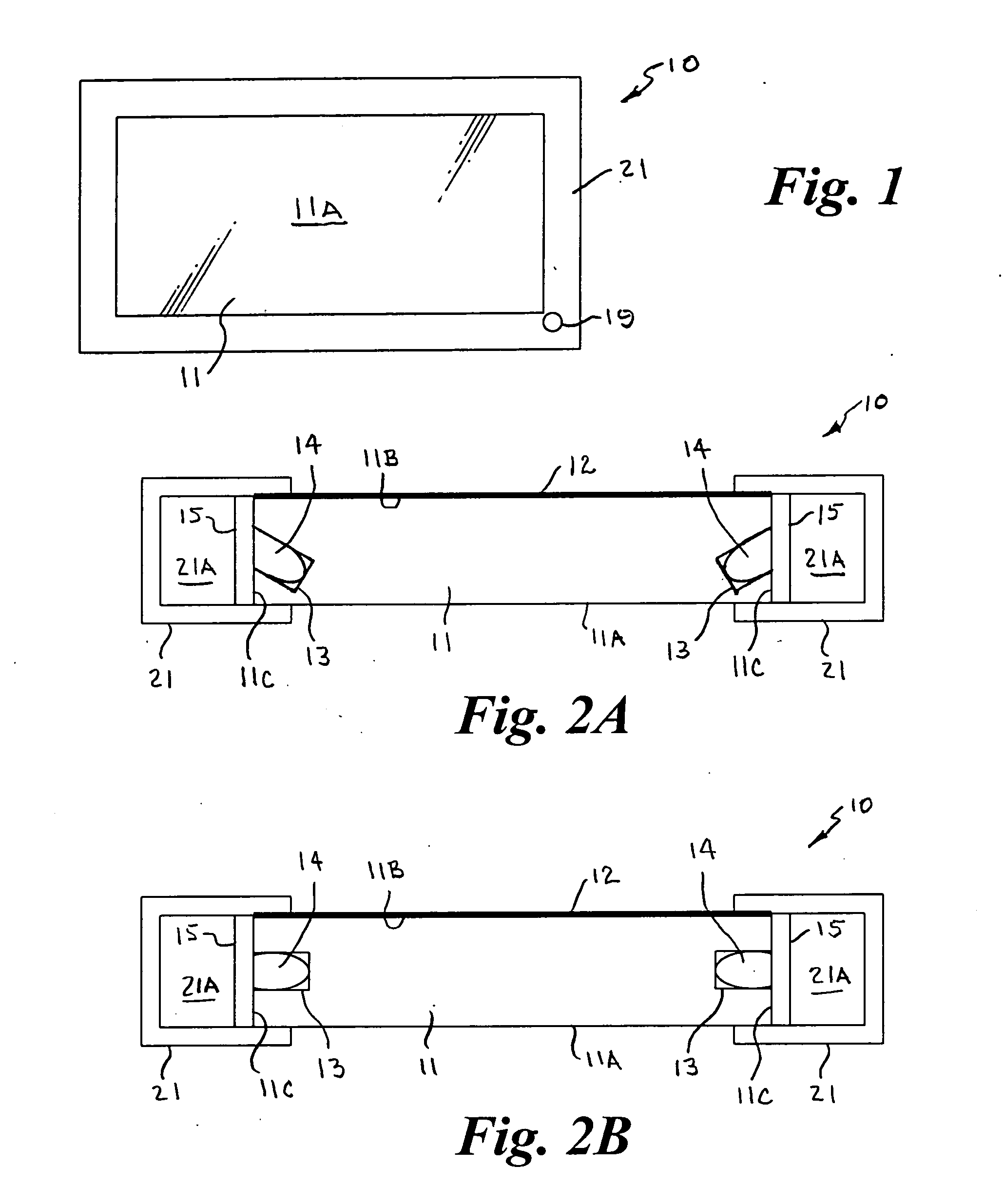
[0036] Referring to the drawings by numerals of reference, there is shown in FIGS. 1 and 2, a preferred light fixture apparatus 10 in accordance with the present invention. The light fixture is shown in and described for purposes of example, as a ceiling fixture adapted to be fitted into or onto the ceiling, however, it should be understood that the fixture may be supported in other ways such as mounting on a wall or other suitable support.

[0037] The fixture 10 has a flat generally rectangular panel 11 formed of a lightweight translucent material with suitable opacity for the transmission of light, surrounded on its outer periphery by a frame 21. In a preferred embodiment, the panel 11 is relatively thin, for example from about ⅜″ to ½″ in thickness, and in the embodiment for use as a ceiling fixture may be from about 10 inches to about 24 inches wide and about 4 feet long. They may also be provided in smaller segments or in elongate narrow strips. It should be understood that the ...


PUM


Abstract

A flat planar light fixture formed of a translucent panel with suitable opacity for the transmission of light is illuminated by a plurality of high brightness LEDs disposed along the edges thereof. A layer of reflective material on a back surface of the panel facilitates reflection and dispersion of light that occurs within the panel through a front surface thereof. The LEDs are powered by low-voltage direct current and coupled with an emergency backup battery that is maintained in a charged condition by household current. The light fixture may be operatively connected with a signal receiver that controls the light intensity and turns the LEDs on and off responsive to signals transmitted from a remote signal transmitter. The LEDs may be provided in different colors to allow the user to vary the color of illumination. The light fixture may also be operatively connected with an alarm system.

Description

CROSS REFERENCE TO RELATED APPLICATION [0001] This application claims priority of U.S. Provisional application Ser. No. 60 / 557,848, filed Mar. 31, 2004.BACKGROUND OF THE INVENTION [0002] 1. Field of the Invention [0003] This invention relates generally to lighting fixtures, and more particularly to a lighting fixture illuminated by a plurality of light emitting diodes wherein the light that is within the panel is transmitted through a front surface thereof. [0004] 2. Background Art [0005] Conventional ceiling mounted light fixtures typically employ incandescent or fluorescent light sources. Incandescent illumination systems have significant disadvantages since they consume a lot of power and produce a great deal of heat, are relatively inefficient and fragile, and require frequent replacement. Systems using fluorescent light sources also have several disadvantages since they require complicated circuitry including a ballast reactor (a coil of wire wrapped around a heavy iron core), ...

Claims


Application Information

Patent Timeline
IPC IPC(8): F21S8/04F21S9/02F21S10/02F21V7/04F21V8/00F21V9/40F21V23/04G02B6/00H05B37/02
CPCF21S8/04F21V2200/30F21S10/02F21V9/10F21V23/0435F21Y2101/02F21Y2105/00G02B6/0021G02B6/0055G02B6/0068H05B33/0857H05B37/0272Y02B20/383F21V2200/20F21S9/022F21Y2115/10H05B45/20H05B47/19Y02B20/30
Inventor SCHEXNAIDER, CRAIG J.
Owner SCHEXNAIDER CRAIG J
Why Eureka
Try Eureka