Layer 2 loop detection system

a detection system and layer 2 technology, applied in the field of layer 2 loop detection system, can solve the problems of failure such as response degradation or meltdown, unavoidable loop occurrence, and inability to identify the location of failur

Inactive Publication Date: 2005-10-06
FUJITSU LTD
View PDF5 Cites 43 Cited by
  • Summary
  • Abstract
  • Description
  • Claims
  • Application Information

AI Technical Summary

Benefits of technology

[0013] The present invention has an object to provide a technique that enables reliable layer 2 loop de

Problems solved by technology

This is because Media Access Control (MAC) frames have no equivalent of the Time to Live (TTL) under the Internet Protocol (IP), so that if a network is looped, this results in a situation where the MAC frames are infinitely circulated at a location at which the network is looped.
Once the STP is collapsed, the blocking port is lost, so that a loop occurrence becomes unavoidable.
As a result, the lay

Method used


Image

  • Layer 2 loop detection system
  • Layer 2 loop detection system
  • Layer 2 loop detection system

Examples


first embodiment

(System Configuration)

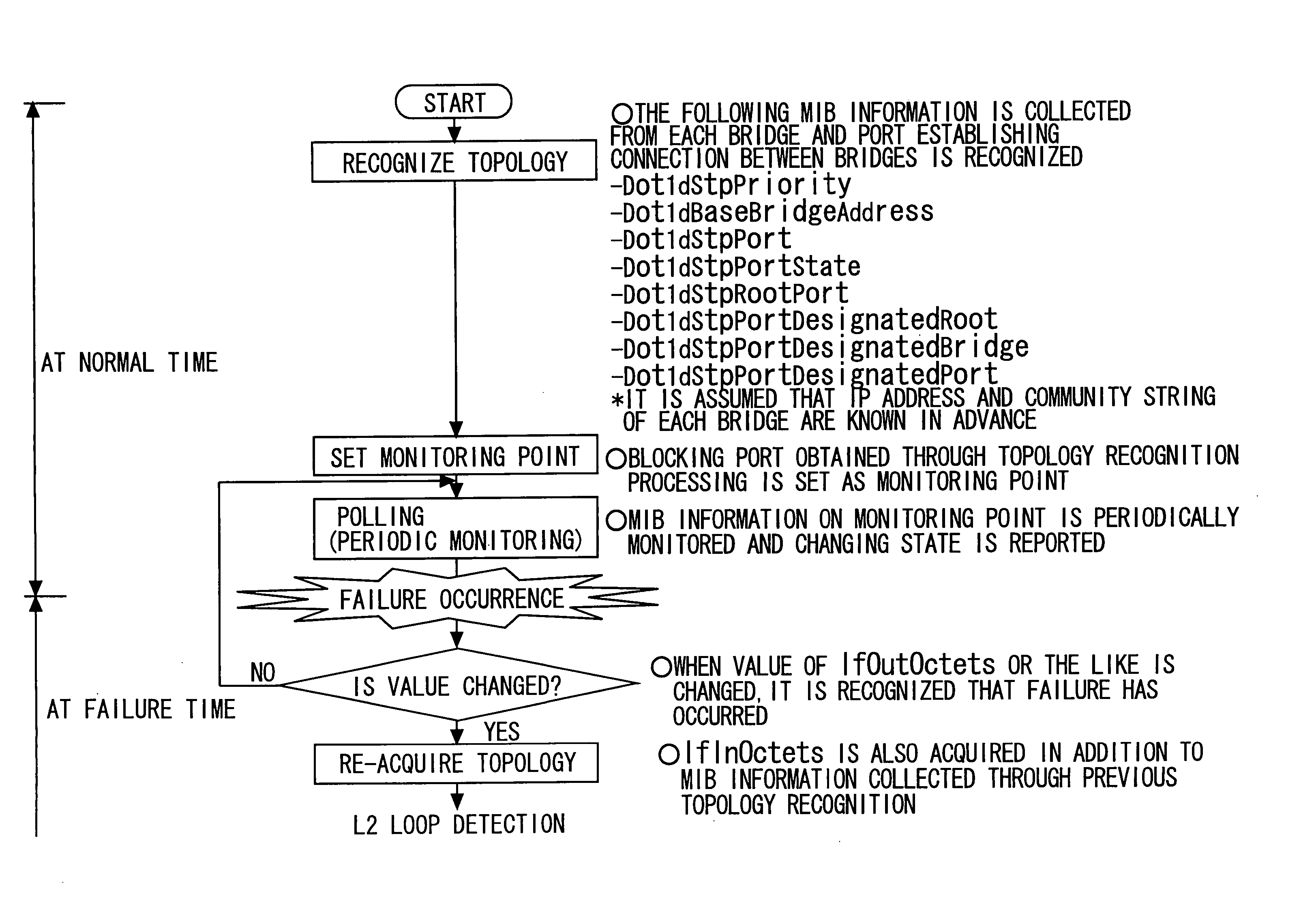
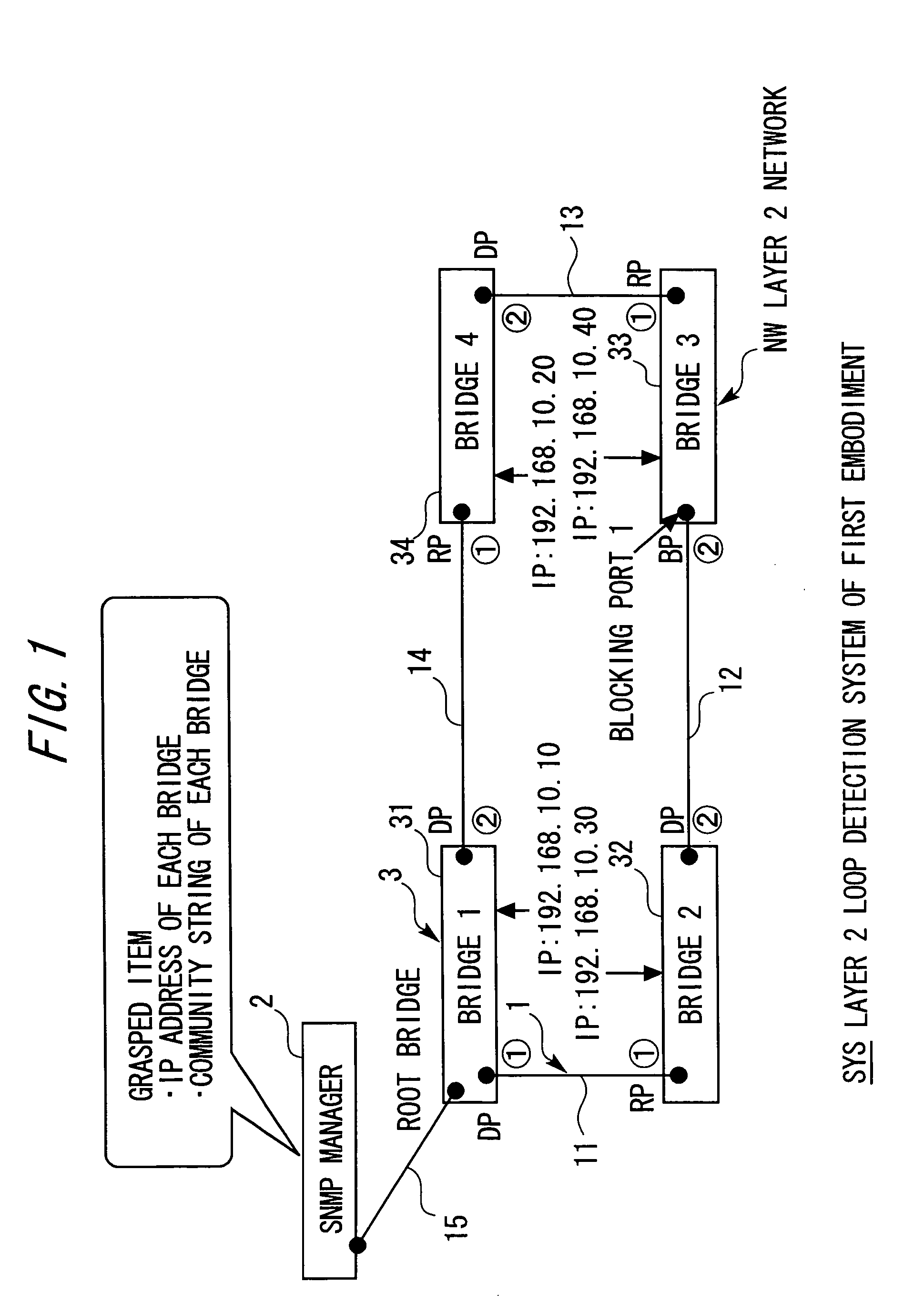
[0045] Referring to FIG. 1 that shows a configuration of a system in a first embodiment of the present invention, a layer 2 loop detection system SYS has the manager / agent structure under the Simple Network Management Protocol (SNMP), includes an SNMP manager 2 and multiple agents 3 (31, 32, 33, 34) that are connected to Local Area Networks (LANs) 1 (11, 12, 13, 14, 15) (such as Ethernet networks (Ethernet: registered trademark)) serving as Internet Protocol (IP) networks, and constructs a system having a network management (monitoring) function.

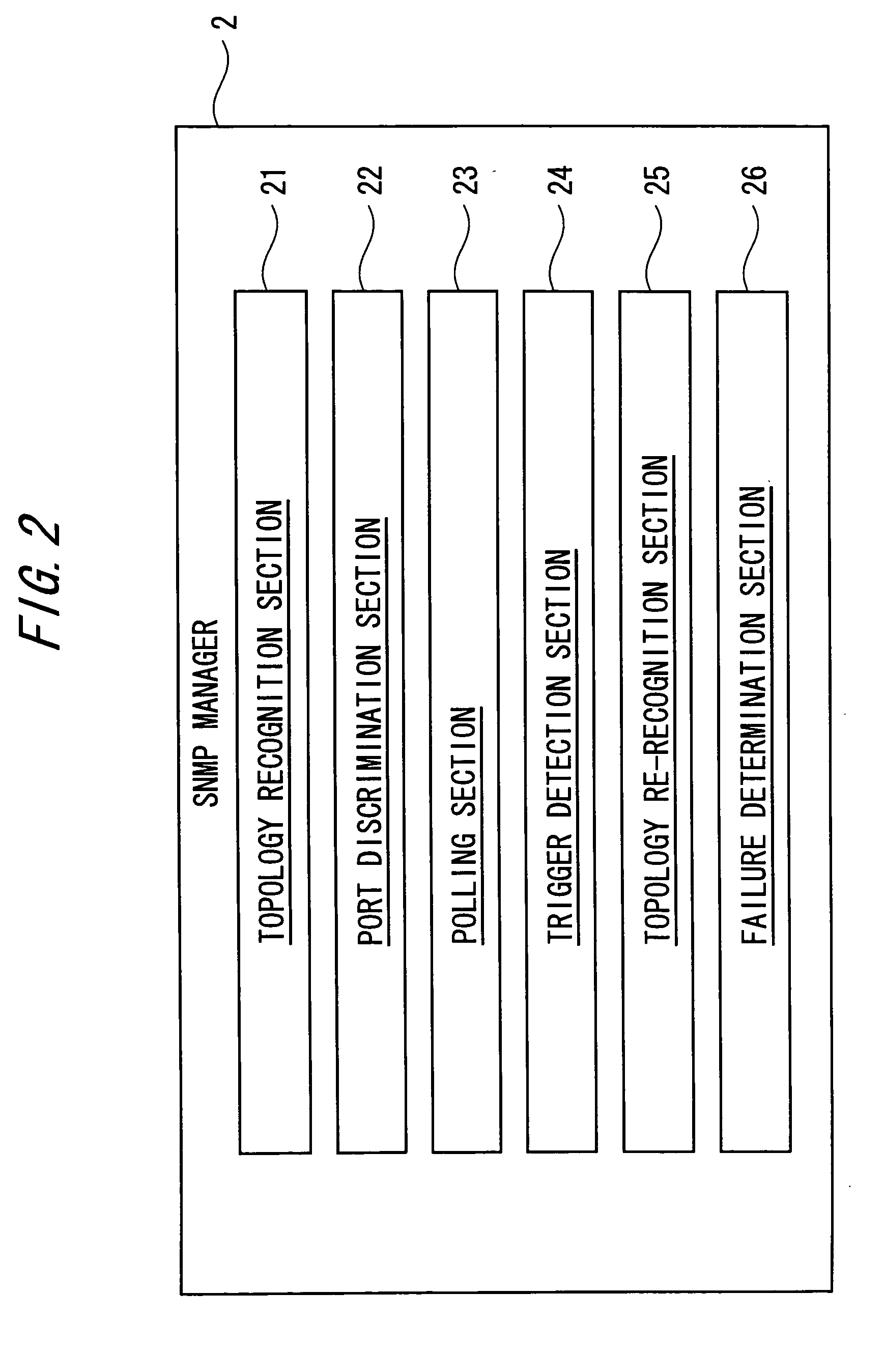
[0046] Strictly speaking, the SNMP manager (hereinafter simply referred to as the “manager” in some cases) 2 on a management (monitoring) station is an apparatus (such as a personal computer (PC)), on which the SNMP manager has been installed, and constructs a layer 2 (L2) loop detection apparatus in this example. The SNMP manager 2 monitors the LANs 1 and the multiple agents 3 on a layer 2 (L2) network NW that is a ...

second embodiment

(System Configuration)

[0084] Referring to FIG. 5 that shows a configuration of a system in a second embodiment of the present invention, like the system SYS of the first embodiment described above, a layer 2 loop detection system SYS of this embodiment has the manager / agent structure under the SNMP, includes an SNMP manager 2 and multiple agents 3 (31, 32, 33, 34) that are connected to Local Area Networks (LANs) 1 (11, 12, 13, 14, 15) (such as Ethernet networks (Ethernet: registered trademark)) serving as IP networks, and constructs a system having a network management (monitoring) function.

[0085] Strictly speaking, the SNMP manager 2 on a management (monitoring) station is an apparatus (such as a personal computer (PC)), on which the SNMP manager has been installed, and constructs an L2 loop detection apparatus in this example. The SNMP manager 2 monitors the LANs 1 and the multiple agents 3 on an L2 network NW that is a management (monitoring) target system. As FIG. 2 shows a d...

third embodiment

(System Configuration)

[0112] Referring to FIG. 8 that shows a configuration of a system in a third embodiment of the present invention, like the system SYS of the first embodiment described above, a layer 2 loop detection system SYS of this embodiment has the manager / agent structure under the SNMP, includes an SNMP manager 2 and multiple agents 3 (31, 32, 33, 34) that are connected to Local Area Networks (LANs) 1 (11, 12, 13, 14, 15) (such as Ethernet networks (Ethernet: registered trademark)) serving as IP networks, and constructs a system having a network management (monitoring) function.

[0113] Strictly speaking, the SNMP manager 2 on a management (monitoring) station is an apparatus (such as a personal computer (PC)) on which the SNMP manager has been installed, and constructs an L2 loop detection apparatus in this example. The SNMP manager 2 monitors the LANs 1 and the multiple agents 3 on an L2 network NW that is a management (monitoring) target system. As shown in FIG. 2 th...


PUM


Abstract

A layer 2 loop detection apparatus includes a unit recognizing a topology of an L2 network at normal time by collecting MIB information including information concerning ports of a plurality of L2 switches from the plurality of L2 switches through SNMP communication; a unit discriminating, based on a topology recognition processing, a blocking port for traffic blocking and a disable port under a port disable state each set under a Spanning Tree Protocol (STP); a unit setting each of the blocking port and the disable port as a monitoring point and periodically monitoring a state thereof; and a unit performing detection of an L2 loop by re-collecting a part of the MIB information from the plurality of L2 switches through SNMP communication and re-recognizing the topology of the L2 network, the detection of the L2 loop detection being triggered by a change of a state of one of the blocking port and the disable port.

Description

BACKGROUND OF THE INVENTION [0001] The present invention relates to a layer 2 loop detection system that enables layer 2 loop detection by an Simple Network Management Protocol (SNMP) manager that monitoring target is a layer 2 network having multiple layer 2 switches. [0002] In a layer 2 network for constructing an enterprise network or the like, as one technique of securing redundancy of the network through loop (layer 2 loop) elimination, the Spanning Tree Protocol (STP) standardized by Institute of Electrical and Electronics Engineers (IEEE) 802.1D is caused to run. [0003] This is because Media Access Control (MAC) frames have no equivalent of the Time to Live (TTL) under the Internet Protocol (IP), so that if a network is looped, this results in a situation where the MAC frames are infinitely circulated at a location at which the network is looped. [0004] Under the STP, by exchanging packets for monitoring so-called “Bridge Protocol Data Unit (BPDU)” between adjacent nodes (lay...

Claims


Application Information

Patent Timeline
IPC IPC(8): H04L12/24H04L12/26H04L12/44
CPCH04L12/462H04L41/0213H04L41/046H04L45/18H04L41/12H04L43/10H04L45/00H04L41/06H04L41/34H04L41/344
Inventor SUGITANI, KIICHIMUTOH, RYOUICHINISHI, TETSUYA
Owner FUJITSU LTD
Why Eureka
Try Eureka