
Channel quality estimation method and channel quality estimation apparatus

a channel quality and estimation method technology, applied in the field of radio communication system, can solve the problems of failure of users to enjoy the service of a high data rate, and achieve the effect of high degree of accuracy

Inactive Publication Date: 2005-10-06
SONY CORP
View PDF16 Cites 19 Cited by
  • Summary
  • Abstract
  • Description
  • Claims
  • Application Information

AI Technical Summary

Benefits of technology

[0030] It is an object of the present invention to provide a channel quality estimation method and apparatus by which, in a communication method wherein a pilot channel which transmits a pilot signal whose channel quality is to be referred to and an estimation object channel whose channel quality is to be estimated have different bandwidths (spreading factors), the channel quality of the estimation object channel can be estimated with a high degree of accuracy based on the pilot signal.
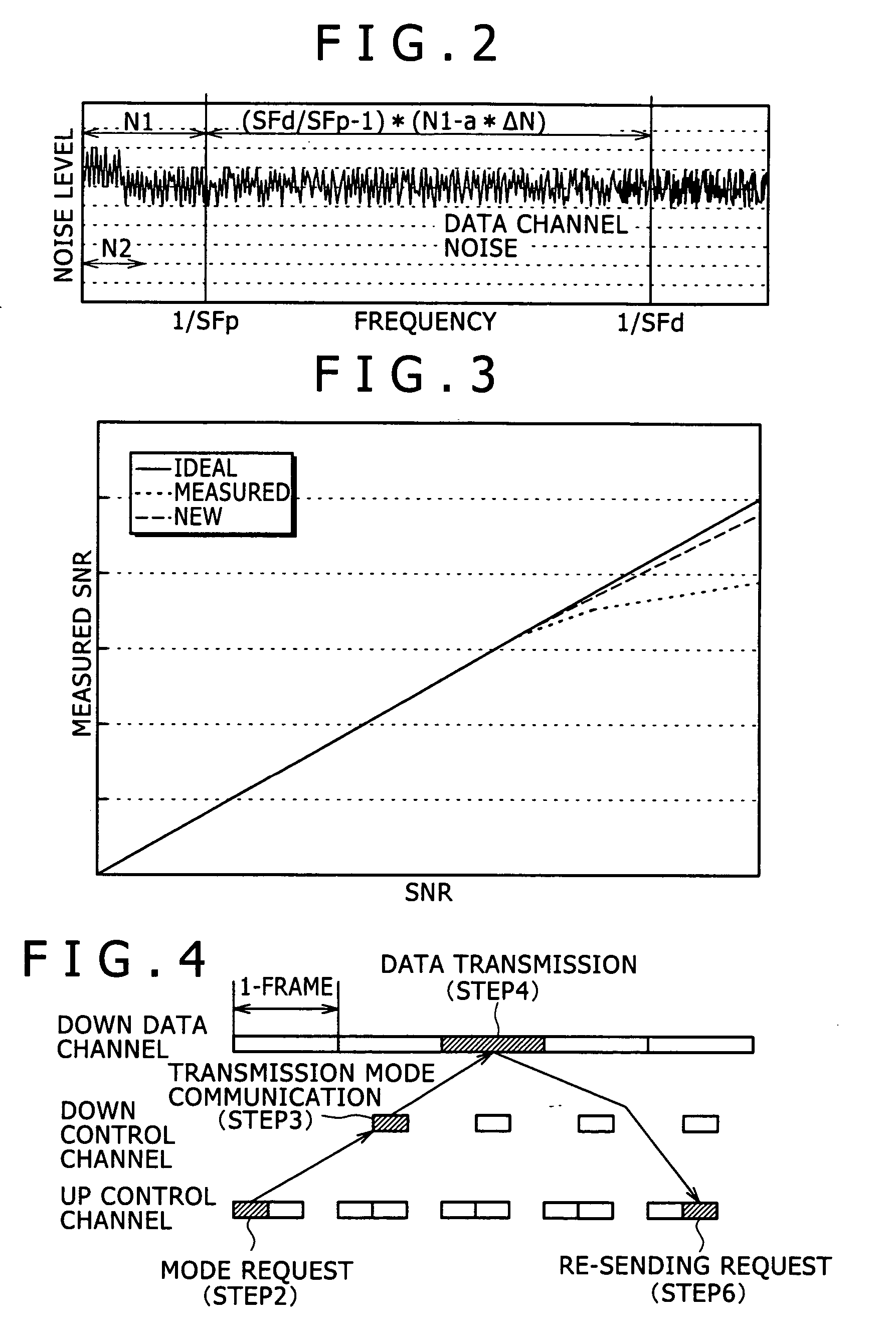
[0036] In the channel quality estimation apparatus, the difference in noise component which depends upon the frequency region is taken into consideration to recognize receiver internal noise which cannot be assumed to be white in the reception pilot signal, and the channel quality of the estimation object channel can be estimated with a high degree of accuracy based on the recognized receiver internal noise. As a result, in applications wherein the channel quality of the data channel is estimated, estimation of the channel quality with a higher degree of accuracy can be anticipated also under high SNR environments, and an adaptive modulation and coding method can be used efficiently.

Problems solved by technology

This causes the amount of the noise in the high frequency region to be estimated to be more than the actual noise amount, resulting in failure of enjoyment by a user of a service of a high data rate which the user can originally enjoy.

Method used


Image

  • Channel quality estimation method and channel quality estimation apparatus
  • Channel quality estimation method and channel quality estimation apparatus
  • Channel quality estimation method and channel quality estimation apparatus

Examples


Embodiment Construction

[0050] In the following, a preferred embodiment of the present invention is described.

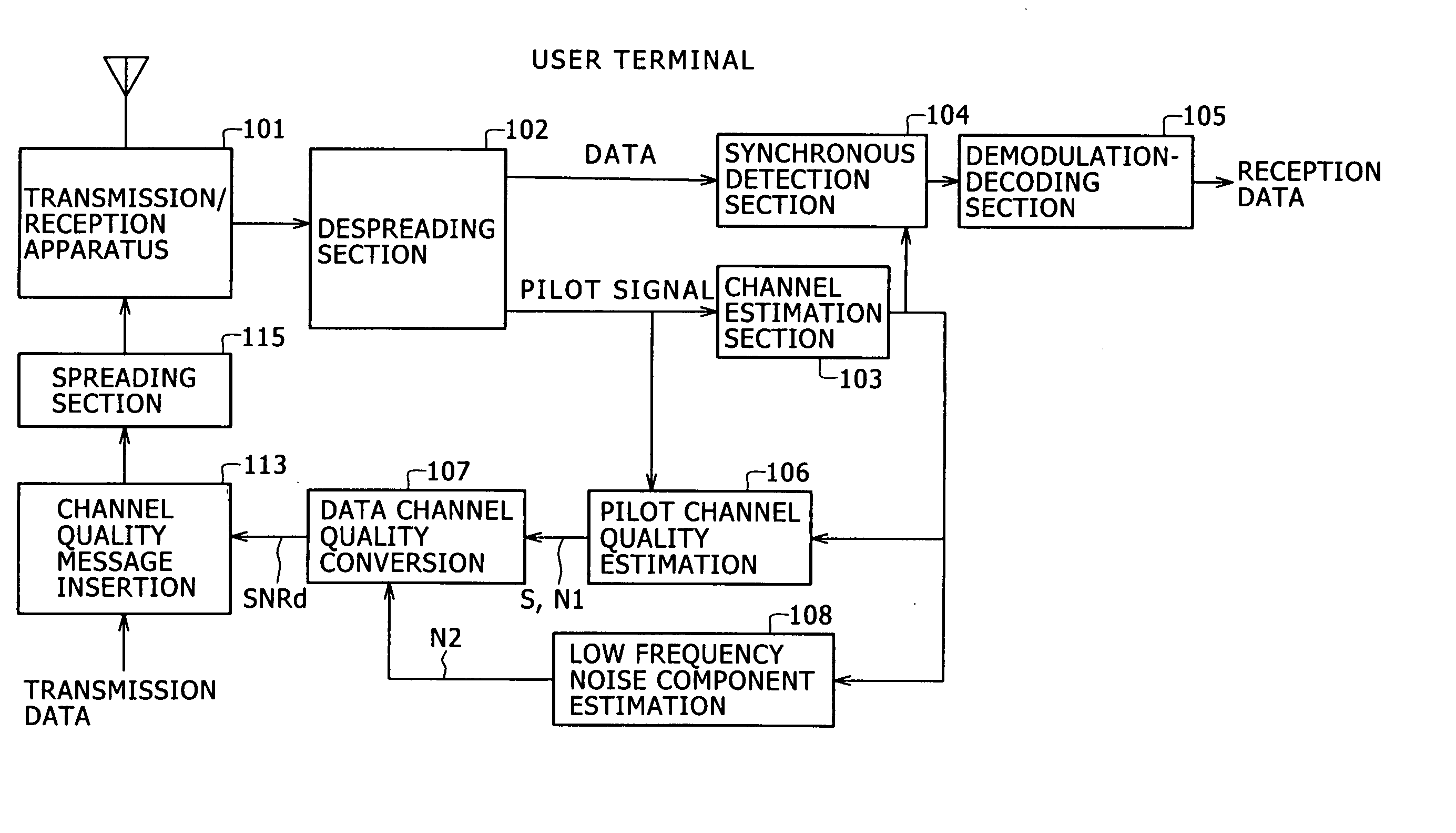
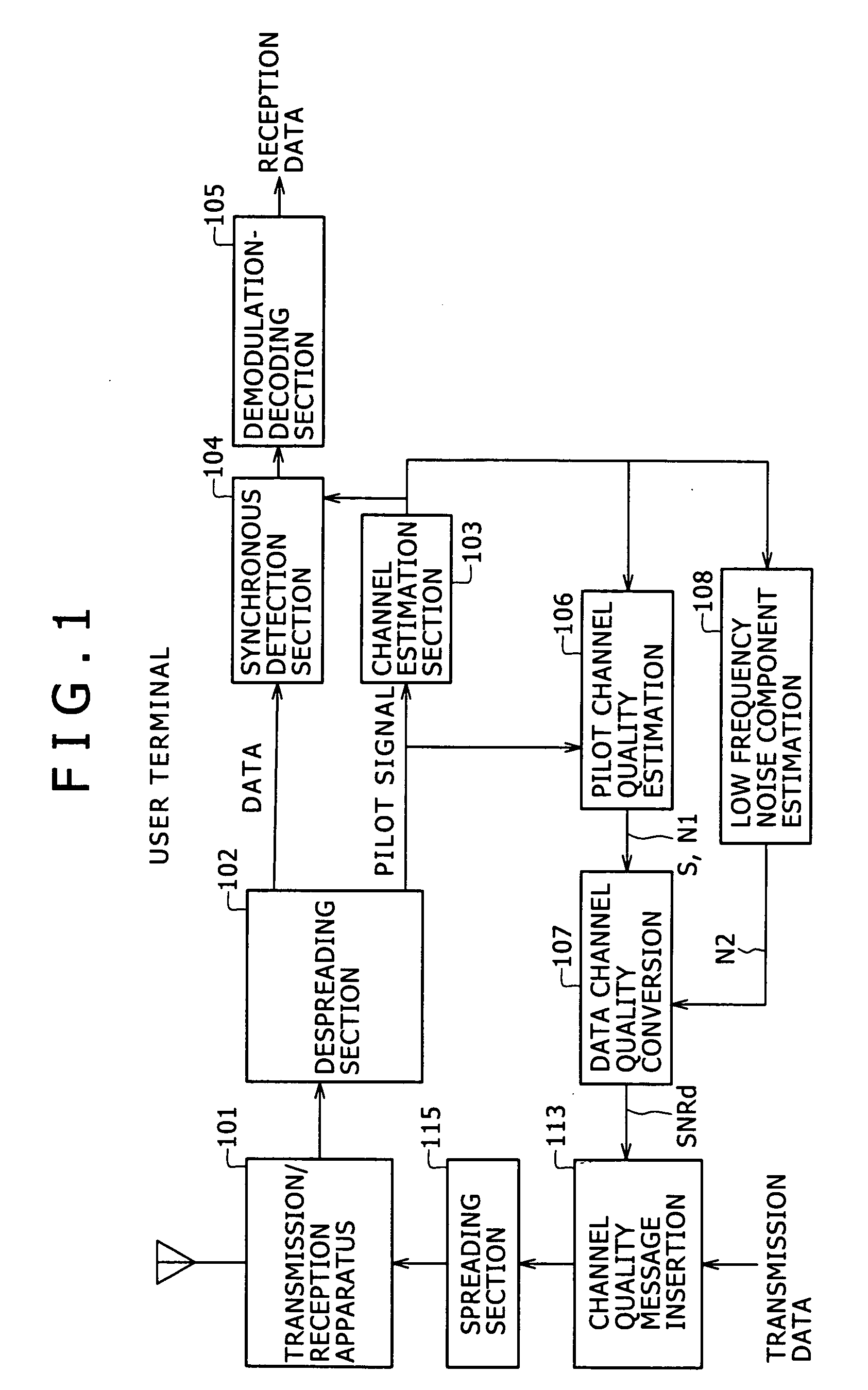
[0051] Referring to FIG. 1, there is shown an example of a configuration of a user terminal used in a radio communication system which uses an adaptive modulation and coding method to implement high-speed data transmission according to the preferred embodiment of the present invention. It is to be noted that a base station used in the radio communication system has such a configuration as described hereinabove with reference to FIG. 5, and overlapping description thereof is omitted herein to avoid redundancy.

[0052] The user terminal shown in FIG. 1 includes a transmission / reception apparatus 101, a despreading section 102, a channel estimation section 103, a synchronous detection section 104, a demodulation-decoding section 105, a pilot channel quality estimation section 106, a data channel quality conversion section 107, a channel quality message insertion section 113, a spreading section 115, a...


PUM


Abstract

A method and apparatus is disclosed by which, in communication wherein a pilot channel for a pilot signal and an estimation object channel have different bandwidths, the channel quality of the estimation object channel can be estimated accurately based on the pilot signal. A despreading section separates data of the object channel and the pilot signal of the pilot channel. A channel estimation section determines a channel estimation value based on the pilot signal. A pilot channel quality estimation section produces signal and noise levels of the pilot channel based on the channel estimation value and the pilot signal. A low frequency noise component estimation section produces a low frequency component of pilot signal noise. A data channel quality conversion section determines the data channel quality based on the outputs of the pilot channel quality estimation section and the low frequency noise component estimation section.

Description

BACKGROUND OF THE INVENTION [0001] This invention relates to a radio communication system which uses an adaptive modulation and coding method to achieve high-speed data transmission. [0002] An adaptive modulation and coding rate communication method for a communication system is generally known wherein the coding rate and the multi-value modulation factor of error correction codes are varied in response to the propagation path quality such that, to a user to whom the propagation quality is high, high-speed data communication is provided while the noise resisting property is sacrificed, but to another user to whom the propagation quality is low, low-speed data communication is provided attaching importance to the noise resisting property. One of such adaptive modulation and coding rate communication methods is disclosed, for example, in Japanese Patent Laid-Open No. 2003-174485. [0003] In recent years, a communication method which uses such adaptive modulation as described above has ...

Claims


Application Information

Patent Timeline
Patent Type & Authority Applications(United States)
IPC IPC(8): H04L1/20H04B1/10H04B1/69H04B1/707H04B7/26H04B17/00H04B17/336H04L1/00H04L1/18H04L25/02H04W24/00H04W28/18H04W88/02H05B3/00
CPCH04B1/1027H04L1/0003H04L1/0009H04B17/309H04L1/20Y02B60/31H04L1/1809Y02D30/50A01B1/08
Inventor ITOH, KATSUTOSHI
Owner SONY CORP
Learn More