Digital video signal encoder and encoding method

a digital video and encoder technology, applied in signal generators with optical-mechanical scanning, color televisions with bandwidth reduction, etc., can solve the problems of thwarting the gradual trend of primary open loop rate control which allows available bandwidth to accumulate or be exceeded, and the reserve available bandwidth is persistently dwindling, so as to improve the quality of motion video images and exceed available bandwidth.

Inactive Publication Date: 2005-10-06
MICROSOFT TECH LICENSING LLC
View PDF60 Cites 51 Cited by
  • Summary
  • Abstract
  • Description
  • Claims
  • Application Information

AI Technical Summary

Benefits of technology

[0012] In accordance with the present invention, a primary open loop rate control selects an optimized quantization parameter Q by determining a desired size for an individual frame and comparing the size of the frame as encoded to the desired size. If the encoded frame size is greater than the desired size, quantization parameter Q is increased to reduce the size of subsequently encoded frames to consume less bandwidth at the expense of image quality. Conversely, if the encoded frame size is less than the desired size, quantization parameter Q is reduced to increase the size of subsequently encoded frames to improve image quality and to fully consume available bandwidth. As a result, each frame is encoded in a manner which maximizes image quality while approaching full consumption of available bandwidth and guarding against exceeding available bandwidth.
[0013] Further in accordance with the present invention, a secondary close loop rate control ensures that overall available bandwidth is never exceeded. Quantization parameter Q is selected by accumulating a bandwidth buffer balance which represents the amount of available bandwidth which has not been consumed by encoded frames of a video image. The bandwidth buffer balance accumulates as time passes and is consumed by encoded frames which are transmitted through the communication medium whose bandwidth is measured. Encoding frames which are consistently slightly too large results in a persistent dwindling of the reserve available bandwidth as represented in the bandwidth buffer balance. In response to the reduction of the bandwidth buffer balance below a predetermined minimum threshold, quantization parameter Q is increased to reduce the size of subsequently encoded frames to consume less bandwidth at the expense of image quality. Encoding frames which are consistently slightly too small results in a persistent accumulation of reserve available bandwidth as represented in the bandwidth buffer balance. In response to the increase in the bandwidth buffer balance above a predetermined maximum threshold, quantization parameter Q is decreased to increase the size of subsequently encoded frames to improve image quality and to fully consume available bandwidth. As a result, gradual trends of the primary open loop rate control which allow available bandwidth to accumulate or to be exceeded are thwarted. In addition, secondary closed loop rate control contributes to selecting an optimum compromise between image quality and available bandwidth.
[0014] Further in accordance with the present invention, motion video images which change from a slow changing scene to a rapidly scene are detected and quantization parameter Q is adjusted to more quickly adapted to the changing motion video signal and to continue to provide a particularly desirable compromise between image quality and available bandwidth. In particular, the absolute pixel difference between two consecutive frames is measured; the absolute pixel difference between the next two consecutive frames is measured; and the difference between the two consecutive absolute pixel differences is determined. If the magnitude of the difference between the differences is greater than a predetermined threshold, it is determined that the rate of change in the motion video signal is changing rapidly and quantization parameter Q is changed accordingly notwithstanding changes to quantization parameter Q as determined by the primary open loop rate control and secondary closed loop rate control described above. In particular, if the difference between the differences is positive, showing an increase in the rate of change between frames, quantization parameter Q is increased to reduce the size of subsequently encoded frames and to thereby make additional bandwidth available for such encoded frames. Conversely, if the difference between the differences is negative, a decrease in the rate of change between frames is detected and quantization parameter Q is decreased to improve image quality and to more fully consume available bandwidth. As a result, the optimum compromise achieved by the primary open loop rate control and the secondary closed loop rate control is more stable, i.e., reaches equilibrium more quickly, when the rate of change between frames of a motion video image changes significantly and rapidly.
[0016] Each of these mechanisms represents a significant improvement over the prior art and enhances the quality of a motion video image without exceeding available bandwidth. These mechanisms can be used individually or in combination.

Problems solved by technology

Encoding frames which are consistently slightly too large results in a persistent dwindling of the reserve available bandwidth as represented in the bandwidth buffer balance.
As a result, gradual trends of the primary open loop rate control which allow available bandwidth to accumulate or to be exceeded are thwarted.

Method used


Image

  • Digital video signal encoder and encoding method
  • Digital video signal encoder and encoding method
  • Digital video signal encoder and encoding method

Examples


Embodiment Construction

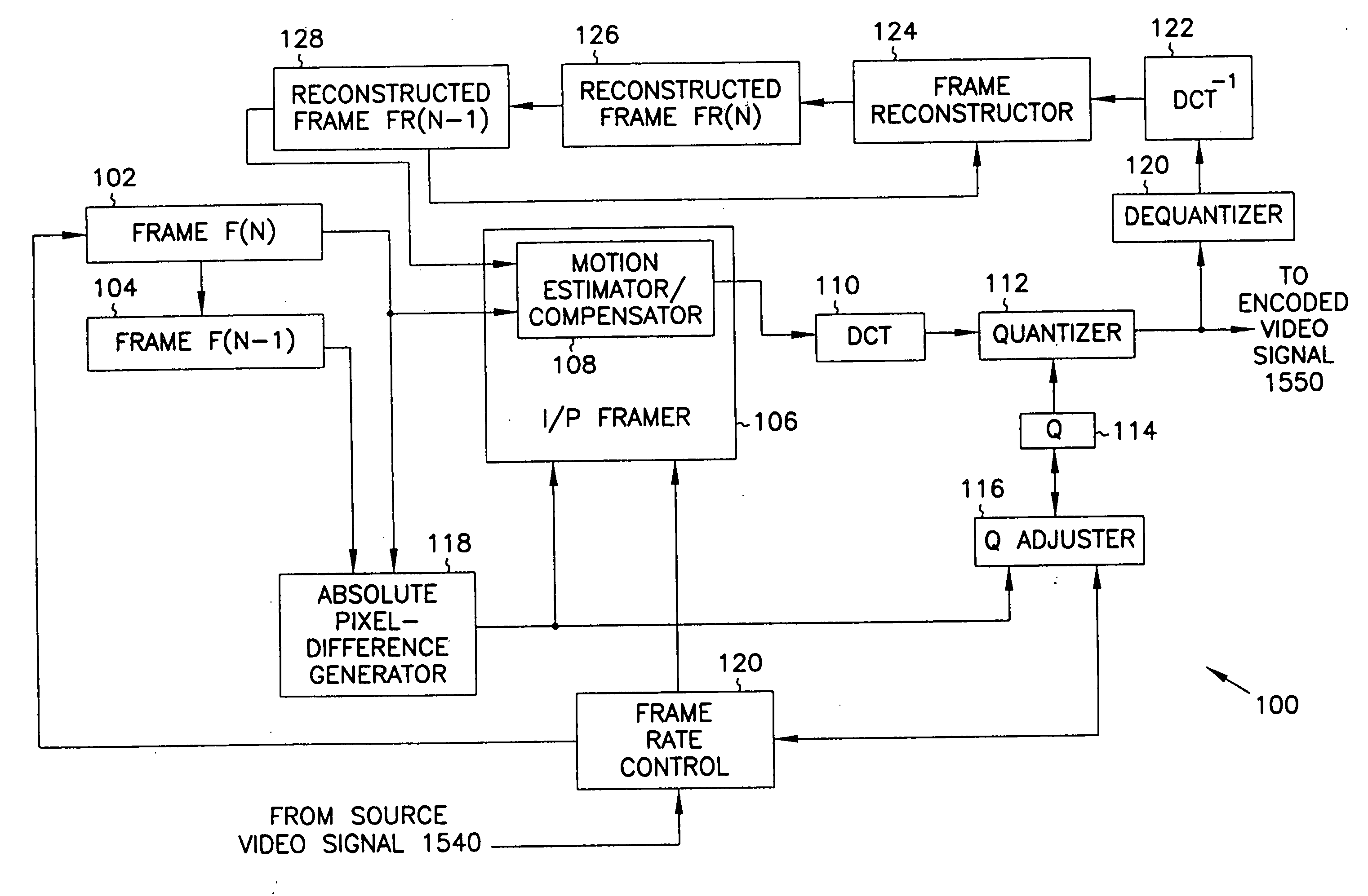
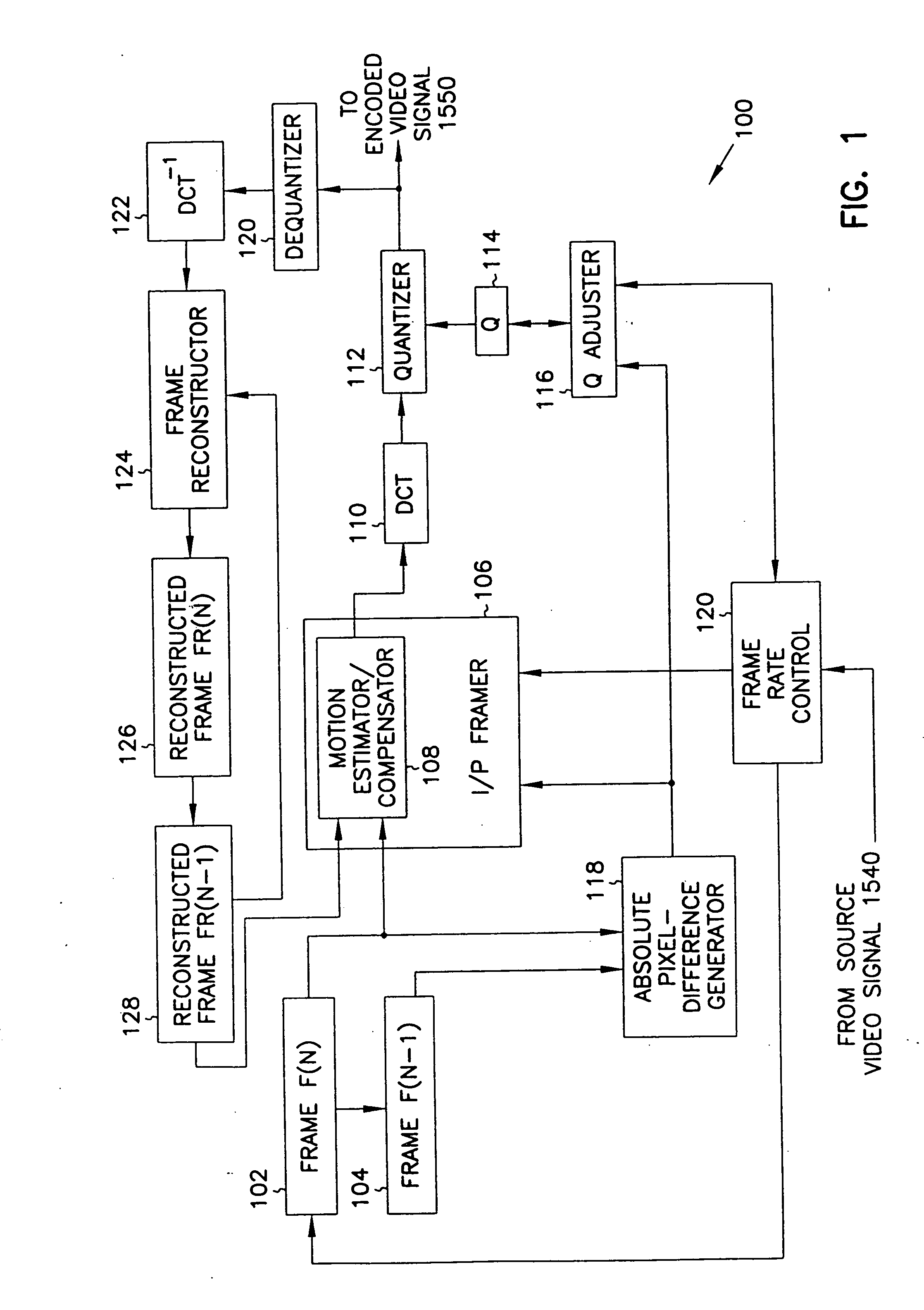
[0030] In accordance with the present invention, a video signal encoder 100 (FIG. 1) maximizes image quality without exceeding bandwidth available for transmitting the encoded motion video signal. Video signal encoder 100 receives a frame of a video signal from a video source (not shown in FIG. 1) which can include, for example, a video camera, a video cassette player, a video laser disk player, or similar video source. Video signal encoder 100 stores the frame in buffer 102 after moving any frame previously stored in buffer 102 into buffer 104. Thus, video signal encoder 100 stores two consecutive frames in buffers 102 and 104. The frame stored in buffer 102 is sometimes referred to herein as the current frame, and the frame stored in buffer 104 is sometimes referred to herein as the previous frame. I / P framer 106 of video signal encoder 100 includes a motion estimator / compensator 108 which retrieves the current frame from buffer 102 and a reconstructed previous frame from a buffer...


PUM


Abstract

A motion video signal encoder maximizes image quality without exceeding transmission bandwidth available to carry the encoded motion video signal by comparing encoded frames of the motion video signal to a desired size of frame. If the size of encoded frames differ from the desired size, quantization is adjusted to produce encoded frames closer in size to the desired size. In addition, a cumulative bandwidth balance records an accumulated amount of available bandwidth. The cumulative bandwidth balance is adjusted as time elapses to add to the available bandwidth and as each frame is encoded to thereby consume bandwidth. If the cumulative bandwidth balance deviates from a predetermined range, quantization is adjusted as needed to either improve image quality to more completely consume available bandwidth or to reduce image quality to thereby consume less bandwidth. Rapid changes in the amount of change or motion in the motion video signal are detected by comparing the amount of change between two consecutive frames and the amount of change between the next two consecutive frames. Quantization is precompensated according to the measured rapid change. Conditional replenishment is improved by dividing macroblocks into quadrants and measuring differences between corresponding quadrants of macroblocks. As a result, sensitivity to changes along edges and corners of macroblocks is increased. In addition, sensitivity to changes in a particular macroblock is increased when an adjacent macroblock contains sufficient change to be encoded and therefore not a candidate for conditional replenishment.

Description

FIELD OF THE INVENTION [0001] The present invention relates to digital video signal compression and, in particular, to a particularly efficient signal encoding mechanism for encoding digital video signals according to digital video standards such as the ITU standard H.263. BACKGROUND OF THE INVENTION [0002] With the advent of digital video products and services, such as Digital Satellite Service (DSS) and storage and retrieval of video streams on the Internet and, in particular, the World Wide Web, digital video signals are becoming ever present and drawing more attention in the marketplace. Because of limitations in digital signal storage capacity and in network and broadcast bandwidth limitations, compression of digital video signals has become paramount to digital video storage and transmission. As a result, many standards for compression and encoding of digital video signals have been promulgated. For example, the lnternational Telecommunication Union (ITU) has promulgated the H...

Claims


Application Information

Patent Timeline
Patent Type & Authority Applications(United States)
IPC IPC(8): H04N7/12H04N7/26H04N7/36H04N7/46H04N7/50
CPCH04N19/147H04N19/172H04N19/114H04N19/126H04N19/19H04N19/142H04N19/177H04N19/179H04N19/137
Inventor WANG, ALBERT S.
Owner MICROSOFT TECH LICENSING LLC
Why Eureka
Try Eureka