Method for creating chemical sensors using contact-based microdispensing technology

a microdispensing and chemical sensor technology, applied in the field of chemical sensors, can solve the problems of inability to reproduce dip coating sensors, inability to offer spatial discrimination of individual sensing layers, and inability to fabricate dip coating sensors in such a manner

Inactive Publication Date: 2005-10-06
LAWRENCE LIVERMORE NAT SECURITY LLC
View PDF31 Cites 74 Cited by
  • Summary
  • Abstract
  • Description
  • Claims
  • Application Information

AI Technical Summary

Benefits of technology

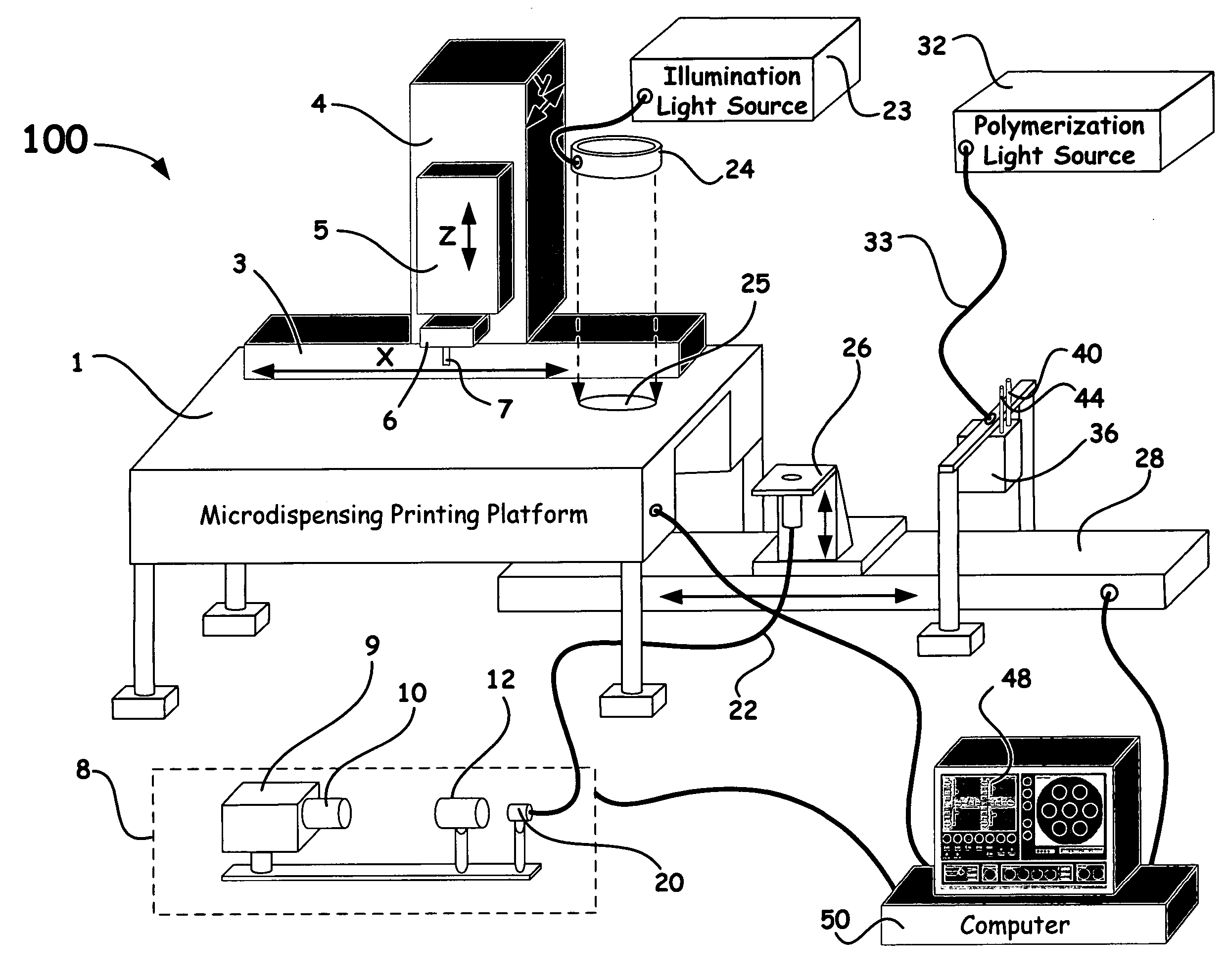
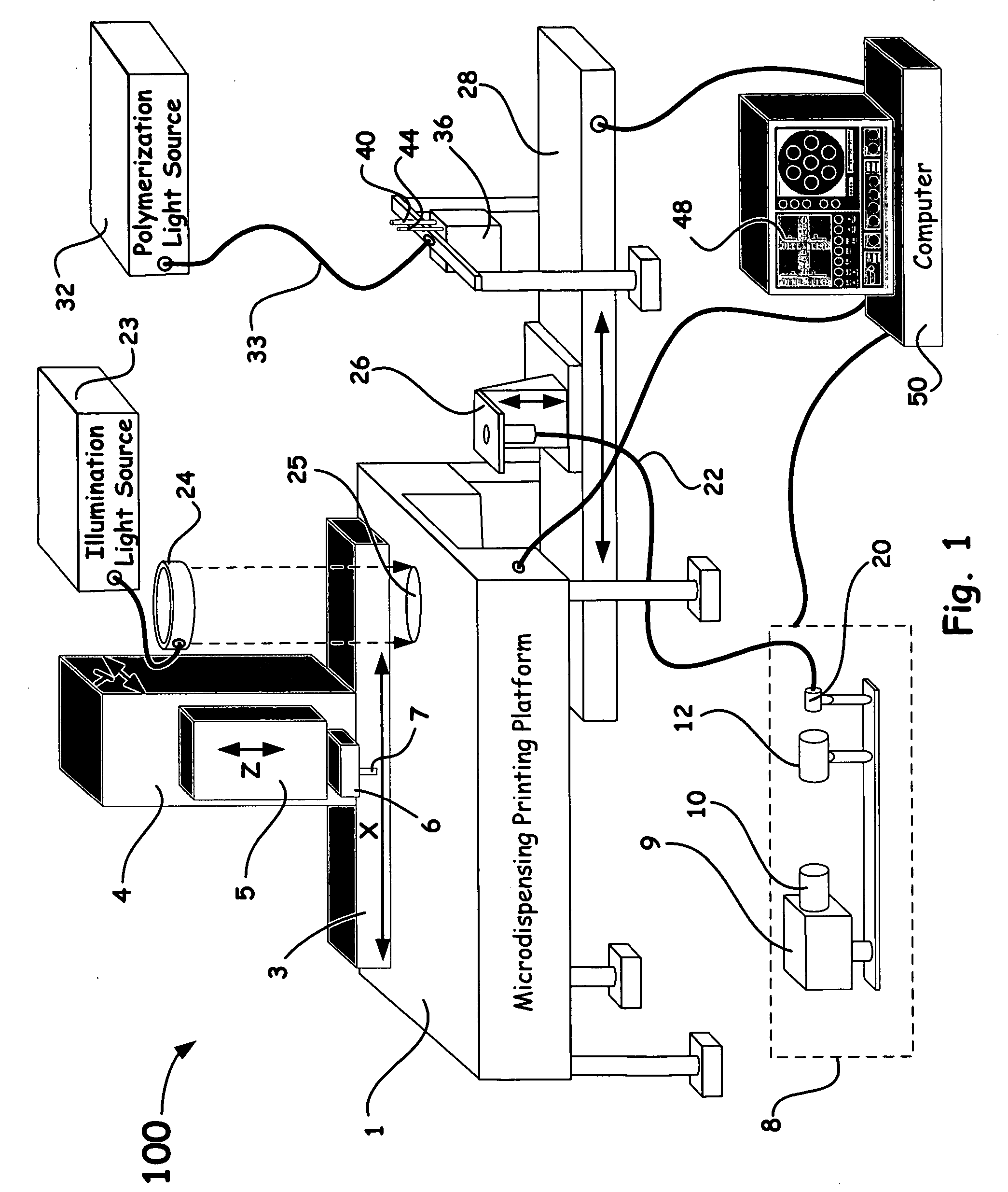
[0014] In the present invention, rigid pin printing tool technology is utilized to apply one or more indicator chemistries on an optical array. Each indicator chemistry can contain one or more light energy absorbing dye(s) whose optical characteristics change in response to a target ligand or analyte of interest. By spectrally monitoring such changes using fluorescence and / or absorption spectroscopy, detection and / or quantitation of the target ligand or analyte is obtained. One or more ligand-specific indicator chemistries are contact printed using rigid pin technology in a known software automated pattern. Simultaneous detection and / or measurement of such ligands or analytes are accomplished using optical imaging techniques to spatially register each microdot.
[0015] In particular, the present invention is directed to a method of producing a chemical sensor that includes: providing an optical array; and contact printing one or more indicator chemistries to the optical array using one or more rigid pin printing tools, wherein the indicator chemistries can optically change due to a detected ligand or analyte of interest.
[0016] Another aspect of the present invention is directed to a chemical sensor production system capable of producing chemical sensors having one or more contact printed indicator chemistries arranged in predetermined patterns; wherein each such indicator chemistries can optically change due to a detected ligand or analyte of interest.
[0017] A further aspect of the present invention is directed to a chemical sensor that includes one or more contact printed indicator chemistries on an optical array; wherein the printed indicator chemistries can optically change due to a detected ligand or analyte of interest.
[0018] Accordingly, the present invention provides chemical sensors and a chemical sensor production system and method for producing such chemical sensors using rigid pin printing tool technology. Such produced sensors have applications in the biomedical, environmental, occupational safety, process control, and biowarfare fields.

Problems solved by technology

However, sensors fabricating in such a manner are limited to single analyte measurements.
Such multianalyte sensor designs can suffer from issues of chemical compatibility and cross sensitivity.
Sensors fabricated by dip coating have not been shown to be reproducible and do not offer spatial discrimination of the individual sensing layers, since each target analyte must interact with the indicator chemistry of a particular layer and produce an optically distinct signal (e.g. fluorescence or absorption).
Furthermore, such arrays are non-uniform, resulting from the lack of control during the photopolymerization step.
This leads to sensors that are not reproducible in their response.

Method used


Image

  • Method for creating chemical sensors using contact-based microdispensing technology
  • Method for creating chemical sensors using contact-based microdispensing technology
  • Method for creating chemical sensors using contact-based microdispensing technology

Examples


Embodiment Construction

[0024] Referring now to the following detailed information, and to incorporated materials; a detailed description of the invention, including specific embodiments, is presented.

[0025] Unless otherwise indicated, numbers expressing quantities of ingredients, constituents, reaction conditions and so forth used in the specification and claims are to be understood as being modified by the term “about.” Accordingly, unless indicated to the contrary, the numerical parameters set forth in the specification and attached claims are approximations that may vary depending upon the desired properties sought to be obtained by the subject matter presented herein. At the very least, and not as an attempt to limit the application of the doctrine of equivalents to the scope of the claims, each numerical parameter should at least be construed in light of the number of reported significant digits and by applying ordinary rounding techniques. Notwithstanding that the numerical ranges and parameters se...


PUM

PropertyMeasurementUnit
volumeaaaaaaaaaa
diameteraaaaaaaaaa
wavelengthsaaaaaaaaaa

Abstract

Contact based rigid pin tool technology is utilized to print one or more indicator chemistries on an optical array or a disposable sheath configured on such arrays. Each indicator chemistry contains predetermined material, such as, light energy absorbing dye(s), optically responsive particles, etc., whose optical characteristics change in response to the target ligand or analyte. By spectrally monitoring such changes using fluorescence and/or absorption spectroscopy, detection and/or quantitation of the target ligand or analyte can be obtained.

Description

CROSS-REFERENCE TO RELATED APPLICATIONS [0001] This application claims the benefit of U.S. Provisional Application No. 60 / 559,834, filed Apr. 5, 2004, entitled “Method for Creating Chemical Sensors Using Contact-Based Microdispensing Technology”, which is incorporated herein by this reference.[0002] The United States Government has rights in this invention pursuant to Contract No. W-7405-ENG-48 between the United States Department of Energy and the University of California for the operation of Lawrence Livermore National Laboratory.BACKGROUND OF THE INVENTION [0003] 1. Field of Endeavor [0004] The present invention relates to chemical sensors, and more particularly to chemical sensors for detecting and / or analyzing at least one ligand or analyte of interest in a fluid or airborne medium utilizing a contact-based tool technology. [0005] 2. State of Technology [0006] In the mid 1970's researchers began investigating the possibility of using optical fibers in sensing applications for m...

Claims


Application Information

Patent Timeline
Patent Type & Authority Applications(United States)
IPC IPC(8): C12Q1/00G01N21/77G01N33/543
CPCB82Y5/00B82Y10/00B82Y20/00G01N21/77G01N33/54373
Inventor CARTER, J. CHANCECOLSTON, BILLY W. JR.BROWN, STEVE B.WILSON, THOMAS S.SETLUR, UJWAL S.PAULSON, CHRISTINE N.BEARINGER, JANE P.
Owner LAWRENCE LIVERMORE NAT SECURITY LLC
Why Eureka
Try Eureka