
Irrigated catheter having a porous tip electrode
a technology of irrigated catheters and tip electrodes, which is applied in the field of irrigated catheters having porous tip electrodes, can solve the problems of sintered metal particles disintegrating and breaking away from the electrode structure, formation of electrically non-conductive lesion within cardiac tissue, and stagnant area between electrodes and tissue, etc., to achieve the effect of promoting fluid flow, minimizing fluid pressure drop through the material, and improving resistance to disintegration during irrigation
- Summary
- Abstract
- Description
- Claims
- Application Information
AI Technical Summary
Benefits of technology
Problems solved by technology
Method used
Image

Examples
Embodiment Construction
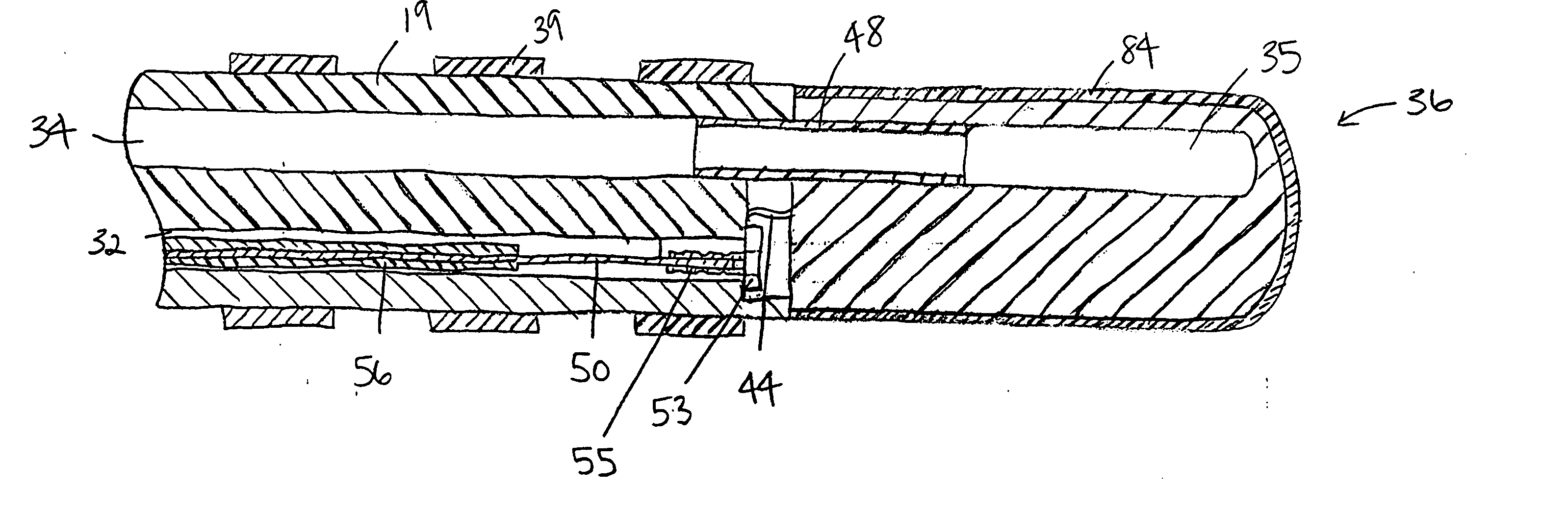
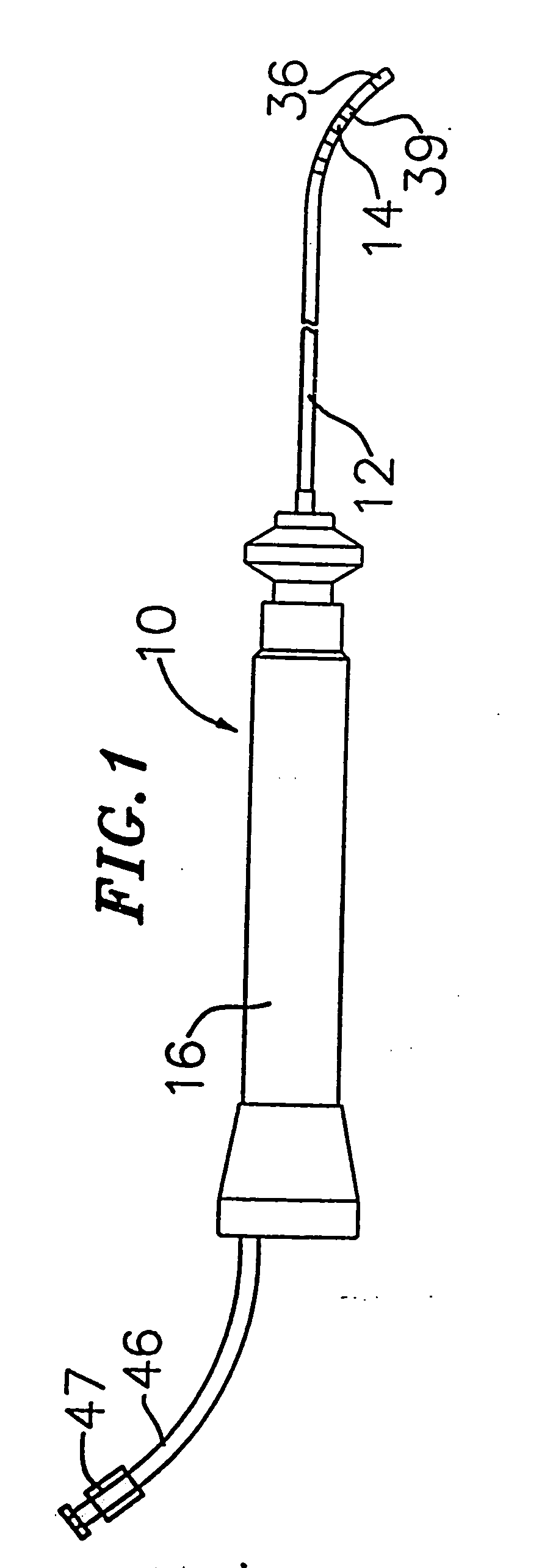
[0026] In a particularly preferred embodiment of the invention, there is provided a steerable catheter having an irrigated tip. As shown in FIGS. 1 to 4, catheter 10 comprises an elongated catheter body 12 having proximal and distal ends, a tip section 14 at the distal end of the catheter body 12, and a control handle 16 at the proximal end of the catheter body 12.
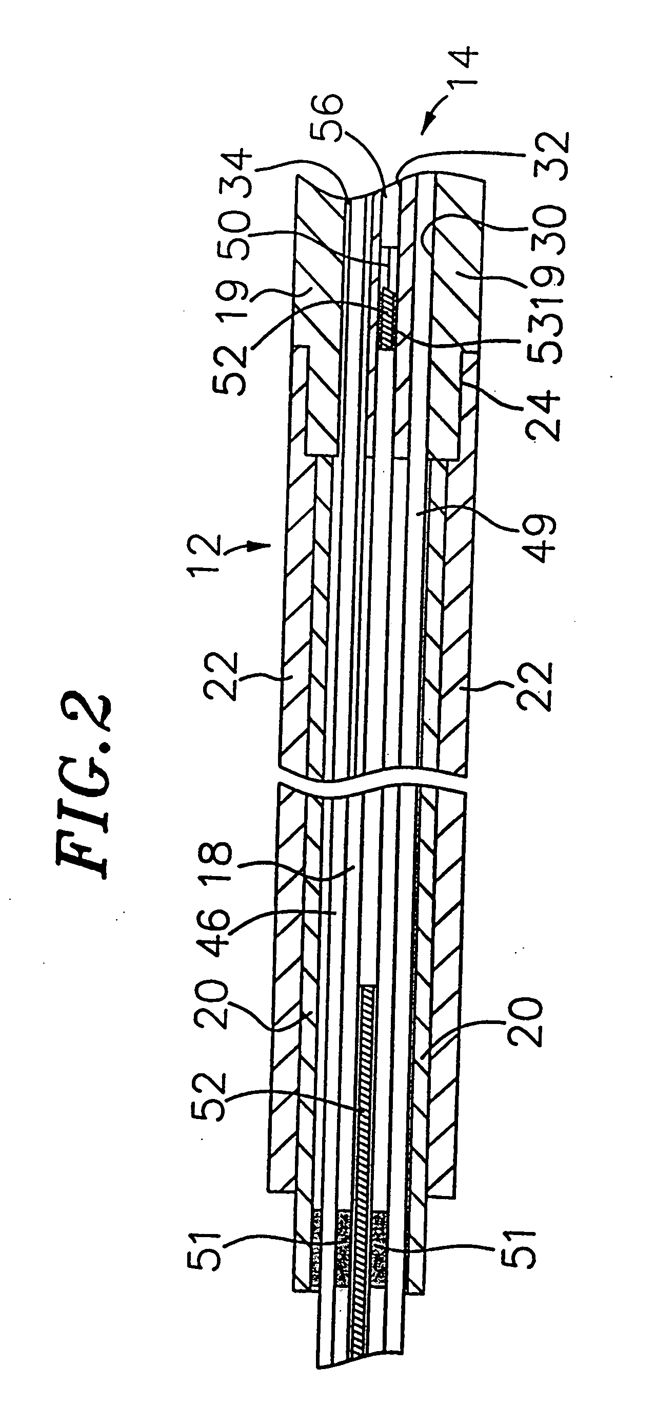
[0027] With reference to FIG. 2, the catheter body 12 comprises an elongated tubular construction having a single, axial or central lumen 18. The catheter body 12 is flexible, i.e., bendable but substantially non-compressible along its length. The catheter body 12 can be of any suitable construction and made of any suitable material. A presently preferred construction comprises an outer wall 22 made of a polyurethane or PEBAX. The outer wall 22 comprises an imbedded braided mesh of high-strength steel, stainless steel or the like to increase torsional stiffness of the catheter body 12 so that, when the control handle 16 i...
PUM
| Property | Measurement | Unit |
|---|---|---|
| temperature | aaaaa | aaaaa |
| diameter | aaaaa | aaaaa |
| diameter | aaaaa | aaaaa |
Abstract
Description
Claims
Application Information