Flexible Pressure Containing Shaped Coverplate Configuration

a flexible pressure and configuration technology, applied in the field of fluid particle contact, can solve the problems of potential leakage opportunities and significant losses, and achieve the effects of reducing the chance of failur

Active Publication Date: 2010-08-19
UOP LLC
View PDF11 Cites 0 Cited by
  • Summary
  • Abstract
  • Description
  • Claims
  • Application Information

AI Technical Summary

Benefits of technology

[0004]The present invention provides for a simpler and less expensive design with a reduced chance of failure, thereby reducing leakage and loss of product. The invention is for a fixed bed reactor with a cross flowing fluid. The fluid is typically a gas. The invention is an apparatus that includes a vertically oriented vessel having a fluid inlet and a fluid outlet. A fluid flows into a centerpipe having a centerpipe radius and is disposed within the vessel, and where the vessel fluid inlet is in fluid communication with a first end of the centerpipe. The centerpipe is made of a perforated material for allowing the fluid to flow across the centerpipe wall, and the centerpipe includes a second end that is restricted to limit flow of fluid, or closed completely to force the fluid through the perforated centerpipe wall. A plug distributor is affixed to the second end of the centerpipe to facilitate a uniform flow of fluid across the centerpipe wall. The apparatus further includes a cylindrical screen with a radius greater than the centerpipe radius and surrounds the centerpipe. The space between the cylindrical screen and the centerpipe is filled with a solid particulate catalyst and forms a catalyst bed. The catalyst bed is sealed at the bottom of the vessel by sealing contact of the centerpipe and screen with the vessel bottom. A toroidal cap is sealingly affixed to the top of the centerpipe and the top of the screen to connect the centerpipe to the screen and to enclose the catalyst bed.

Problems solved by technology

The pressure differential combined with the cyclic thermal operation creates potential leakage opportunities where the leakage of the seal flow has the equivalent effect of a feed bypass.
The conventional system requires the interaction of numerous components at multiple interfaces, and presents the opportunity for mechanical failure and subsequent leakage, resulting in significant losses.

Method used


Image

  • Flexible Pressure Containing Shaped Coverplate Configuration
  • Flexible Pressure Containing Shaped Coverplate Configuration

Examples


Embodiment Construction

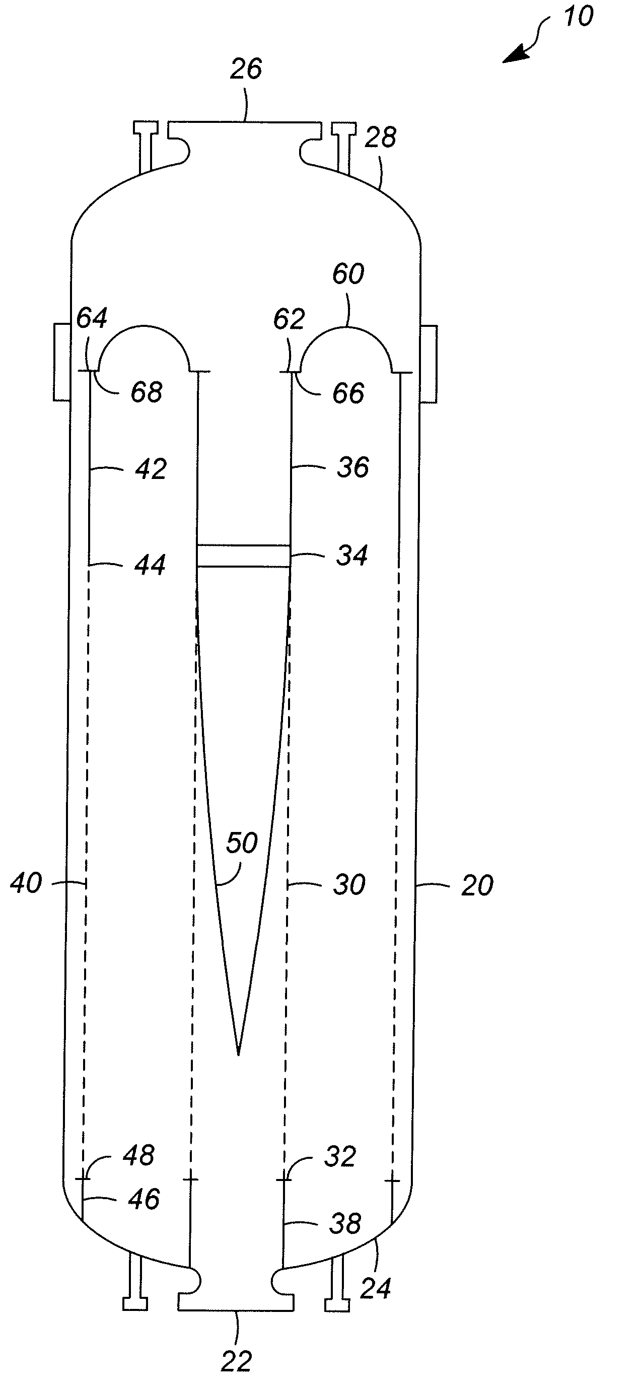
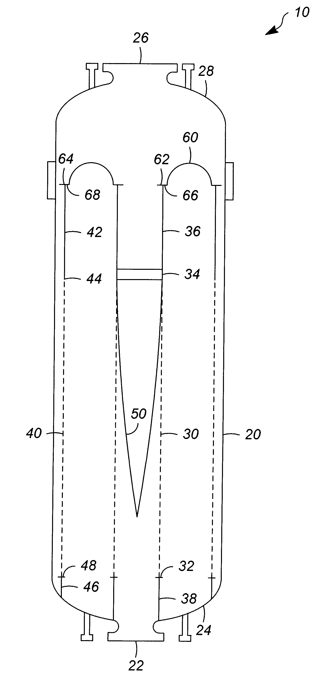
[0007]A new coverplate design is needed to improve the overall performance, and to overcome the deficiencies of the current design that allows for the development of leaks. A new coverplate configuration has been designed that is flexible enough to handle the frequent thermal cycles for the differential growth of the inner and outer screens, and having sufficient strength to contain the differential pressure. The containment of the vapor has been a long term problem, and that the approach has been to continually add more seals and stiffeners to the coverplate to overcome leakage.

[0008]The present invention comprises an apparatus for fluid-solid contacting comprising a vertically oriented, substantially cylindrical vessel having a vessel wall, and a fluid inlet and fluid outlet. The vessel also includes a vessel bottom and a vessel top, comprising elliptically shaped ends affixed to the cylindrical vessel ends. The apparatus further includes a vertically oriented centerpipe having a ...


PUM

PropertyMeasurementUnit
gauge thicknessaaaaaaaaaa
centerpipe radiusaaaaaaaaaa

Abstract

A flexible pressure containment coverplate has been invented for radial flow reactors. The coverplate is for a fixed bed reactor wherein the reactor undergoes significant thermal cycles. The coverplate provides flexibility for axial and radial thermal growth, while providing a sealing capability to prevent leakage of the fluid. The coverplate has a half toroidal structure, with a semi-circular cross-section.

Description

FIELD OF THE INVENTION[0001]This invention relates to the field of fluid particle contacting. In specific the field is for a hydrocarbon stream contacting a fixed bed of solid catalyst particles for the purpose of olefin cracking.BACKGROUND OF THE INVENTION[0002]The olefin cracking process comprises contacting an olefin rich stream with a solid catalyst to crack larger olefins into light olefins. The process increases the yields of ethylene and propylene from processes that generate butenes, pentenes and larger olefins. The olefin cracking process utilizes a radial flow reactor design wherein the olefin rich gas flows radially, or horizontally, over a fixed bed of catalyst. The olefin cracking reactor uses a downflow seal design requiring a coverplate configuration. The coverplate connects the inner and outer screens of the radial flow reactor. This configuration enables vapor containment in a low amplitude-high frequency thermal cyclic operation. The flow of the gas over the reacto...

Claims


Application Information

Patent Timeline
Patent Type & Authority Applications(United States)
IPC IPC(8): B01J19/00
CPCB01J8/008B01J8/0214C10G2400/20C10G49/002C10G2300/1088B01J2208/00884
Inventor VETTER, MICHAEL J.
Owner UOP LLC
Why Eureka
Try Eureka