
Adiabatic multi-bed catalytic converter with inter-bed cooling

a catalytic converter and inter-bed technology, applied in the direction of ammonia preparation/separation, ammonia compounds, chemical production, etc., can solve the problems of complex design and construction, complicated welding, and high cost of multiple catalytic beds, so as to achieve simple and less expensive design, reduce cost, and reduce the effect of cos

Active Publication Date: 2017-06-27
CASALE SA
View PDF12 Cites 2 Cited by
  • Summary
  • Abstract
  • Description
  • Claims
  • Application Information

AI Technical Summary

Benefits of technology

The invention simplifies the design of a converter by using a common heat exchanger for multiple catalytic beds, reducing the number of tube sheets and the cost associated with them. Additionally, multiple detachable catalytic cartridges can be used for existing converters, making the invention more flexible and cost-effective. The invention also allows for inter-bed cooling and maintains compatibility with existing designs. Overall, the invention simplifies the converter design and reduces costs.

Problems solved by technology

A disadvantage of the known converters is that design and construction become sophisticated and expensive with multiple catalytic beds.
For example, each shell-and-tube heat exchanger needs a respective bundle of tubes with two tube sheets; tube sheets are quite expensive items and weldings between tubes and the tube sheet require careful and expensive execution.
The current prior art considers that a layout with more than three beds and two intermediate exchangers is not convenient.

Method used


Image

  • Adiabatic multi-bed catalytic converter with inter-bed cooling
  • Adiabatic multi-bed catalytic converter with inter-bed cooling
  • Adiabatic multi-bed catalytic converter with inter-bed cooling

Examples


Embodiment Construction

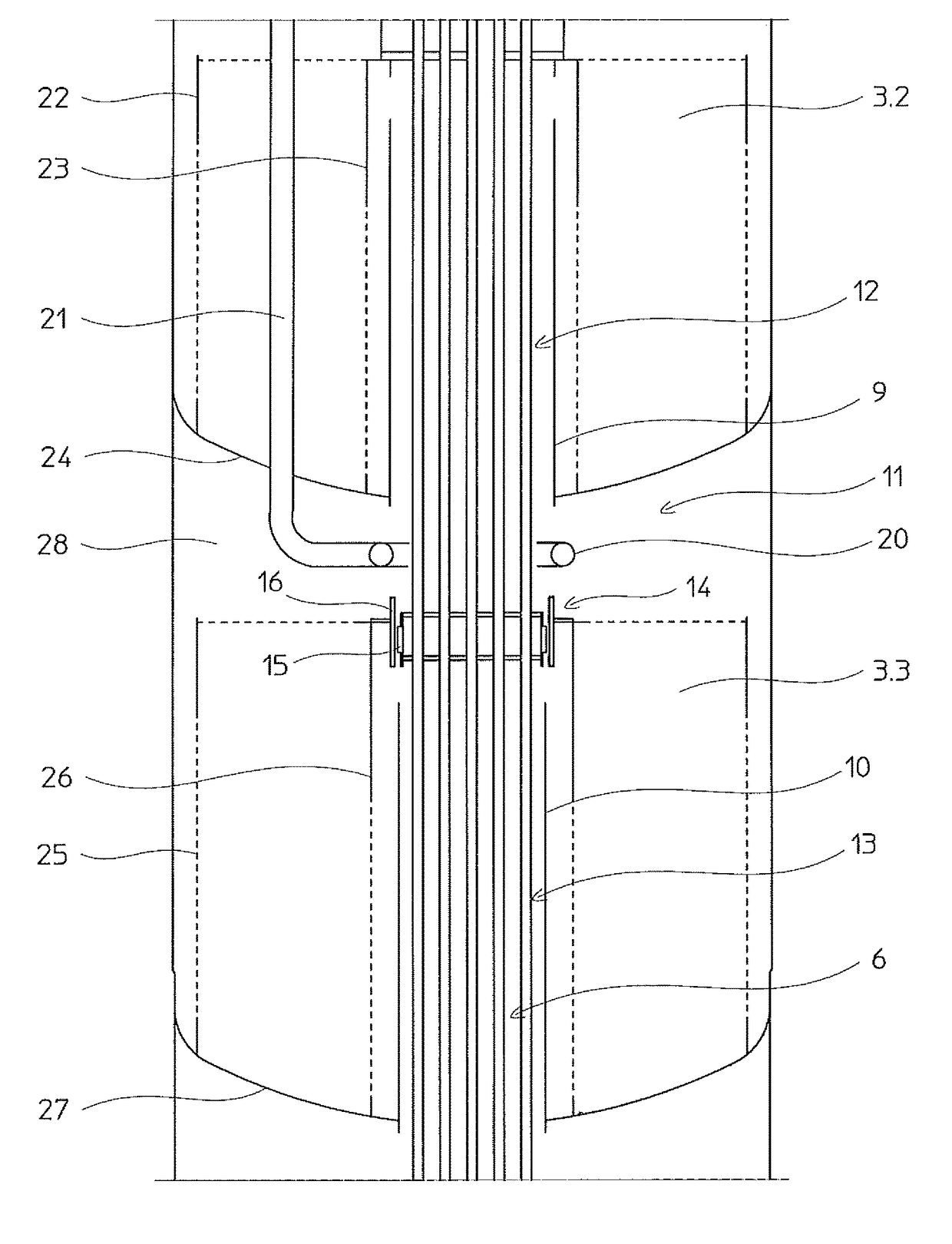
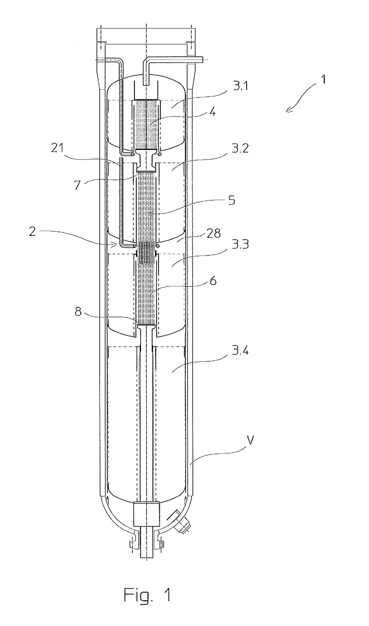
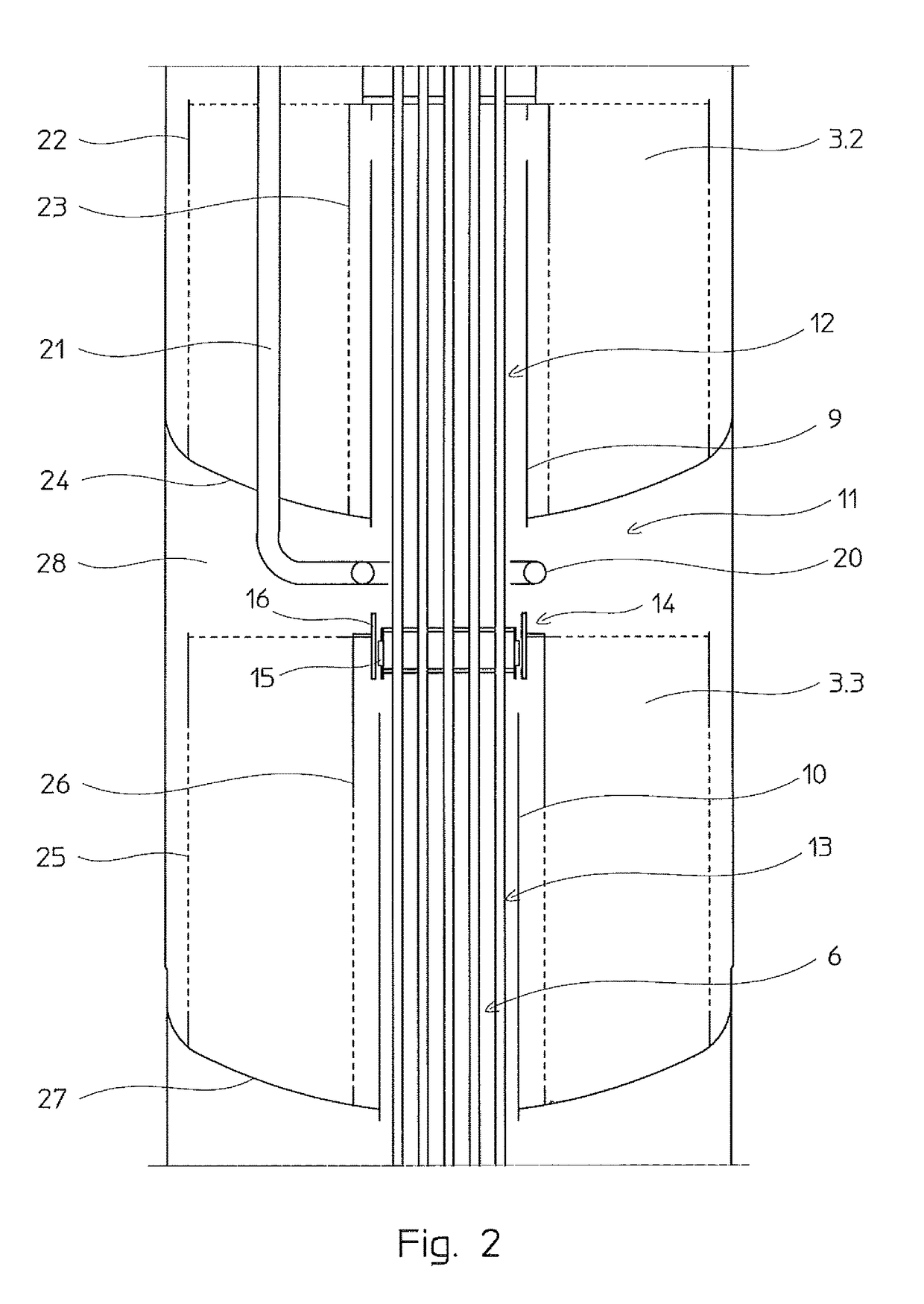
[0030]FIG. 1 discloses a converter 1, for example an ammonia or a methanol converter, comprising a pressure vessel V and a catalytic cartridge 2. Said cartridge 2 is equipped with four catalytic beds denoted with numerals 3.1 to 3.4. The cartridge 2 comprises a suitable basket with side walls and a bottom wall for each catalytic bed, according to known technique which need not be described here. The catalytic beds are arranged in series, that is the effluent leaving a catalytic bed passes to the next catalytic bed for a further step of reaction, possibly after mixing with a quenching gas.

[0031]Each bed is configured with annular cylindrical shape and has a central axial passage; shell-and-tube heat exchangers are arranged in the central passages of at least some of the catalytic beds, to provide inter-bed cooling of the gaseous products evolving from one catalytic bed to another.

[0032]More in detail, referring to FIG. 1 the converter 1 comprises a first heat exchanger 4 arranged ins...


PUM

PropertyMeasurementUnit
elasticaaaaaaaaaa
pressureaaaaaaaaaa
inlet bed temperatureaaaaaaaaaa

Abstract

A multi-bed catalytic converter (1) with inter-bed heat exchangers, comprising a plurality of superimposed catalytic beds and a common heat exchanger (5) which is shared between two or more consecutive catalytic beds, said common heat exchanger including heat exchange bodies such as a tube bundle (6), and a wall system (9, 10) to define a tube side and a shell side respectively, and the shell side comprising at least a first space (12) and a second space (13), wherein the first space (12) receives the product gas leaving the first of said consecutive beds, and the inter-cooled gas leaving said first space (12) is admitted in the second bed (3-3) for further conversion, and a sealing means (14) preventing a direct gas passage from said first space to said second space.

Description

[0001]This application is a national phase of PCT / EP2013 / 074157, filed Nov. 19, 2013, and claims priority to EP 13153127.9, filed Jan. 29, 2013, the entire contents of both of which are hereby incorporated by reference.FIELD OF THE INVENTION[0002]The present invention relates to the field of multi-bed catalytic converters with inter-bed cooling.PRIOR ART[0003]Adiabatic multi-bed catalytic converters are used in several fields, including e.g. the synthesis of methanol and the synthesis of ammonia.[0004]An inter-cooled multi-bed converter comprises a plurality of catalytic beds arranged in series, and one or more inter-bed heat exchangers for cooling the gaseous flow of partially-reacted products (briefly called products) passing from one bed to another.[0005]A common layout can be described as follows. The converter is an elongated vertical pressure vessel hosting a catalytic cartridge; said cartridge includes a plurality of superimposed catalytic beds; each catalytic bed includes an...

Claims


Application Information

Patent Timeline
Patent Type & Authority Patents(United States)
IPC IPC(8): B01J8/04C01C1/04
CPCB01J8/0469B01J8/0415B01J8/0496C01C1/0423B01J2208/00194B01J2208/00814B01J2208/027B01J2219/00024Y02P20/52Y10T29/49346B01J2208/00132
Inventor RIZZI, ENRICOIT), FILIPPI, ERMANNO
Owner CASALE SA
Learn More