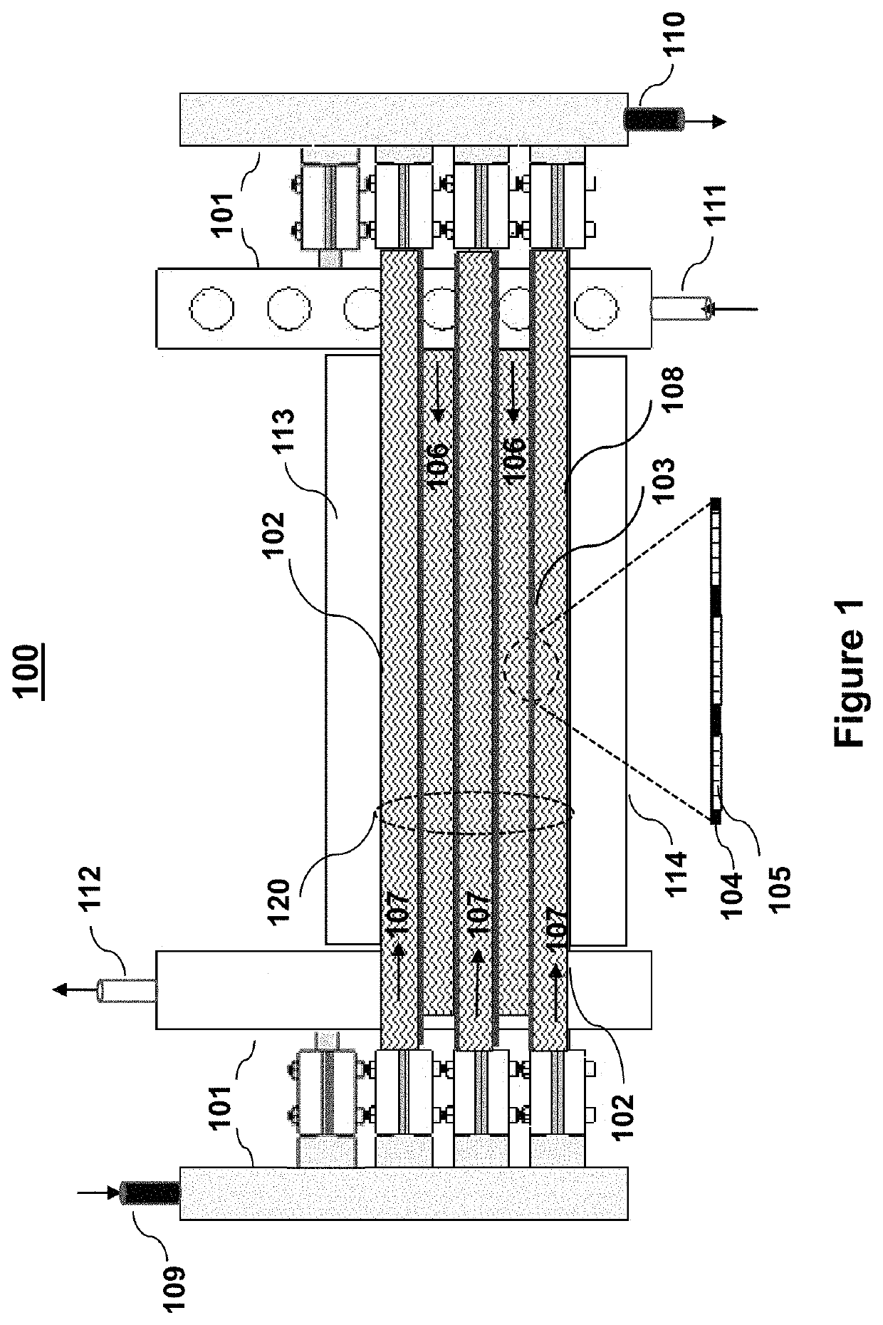
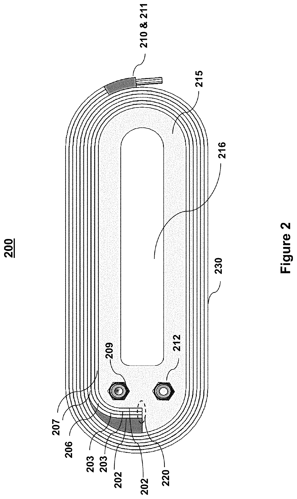
[0024]One aspect of the invention is that the entire PEM fuel cell structure is constructed of layers of flexible materials aligned parallel along their broadside surfaces More specifically, the PEM is mounted on a non-permeable support layer including a semi-permeable PEM (collectively, a separator layer), and sealed between two non-permeable end layers along the periphery thereby creating sealed fluid flow regions (fluid channels, hereinafter) one on either side of the PEM. A fuel flows in one channel, and a reactant fluid flows in the channel on the opposite side of the PEM. The fuel and the reactant are maintained in close proximity of the PEM to facilitate an electrochemical reaction between the fuel and the reactant across the PEM. The channels sharing a common PEM on the opposite sides of the PEM are typically of opposite polarity. Optional gas diffusion layer (GDL) embedded with the PEM further improves the diffusion and therefore, the interaction between the fuel and the reactant across the PEM.
[0025]In another aspect of the invention, the efficiency of the electrochemical reaction is further improved by including a porous material (a mesh hereinafter) in the channels to facilitate uniform flow and efficient diffusion of the reacting species to the PEM. The mesh material acts like a diffusion facilitator to increase the effective surface area for efficient electrochemical reaction in the immediate vicinity of the PEM. The independently sealed channels for carrying the fuel and the reactant each have independent inlet ports to supply the respective fluids, and independent outlet ports to dispose the unused fuel and the reactant, respectively.
[0026]One important design feature of the PEM fuel cell according to this invention is the flexible current collecting layers that are sealed within the channels located in close proximity to the surfaces where the electrochemical reaction takes place. The electrodes attached to these current collecting layers are sealed within the respective channels and are accessible externally to connect to an external load. The electrical design of the fuel cell completely eliminates the need for the current collection plates (bipolar or unipolar) that are essential elements of the large variety of the prior art PEM fuel cell described in the previous section. Thus, the PEM fuel cell according to this invention is very compact, flexible, and light weight for modularly stacking in large numbers to increase the output power.
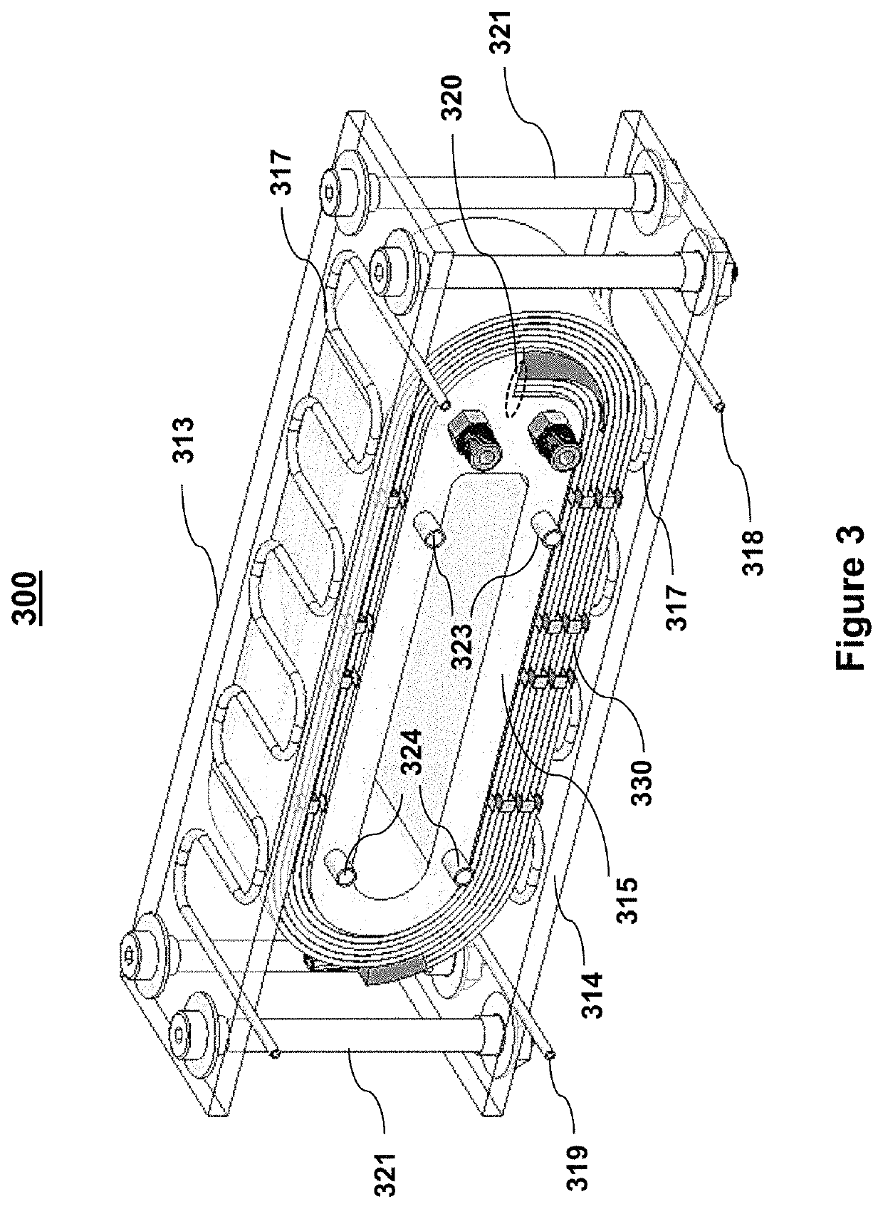
[0027]The flexible design of the PEM fuel cell structure is adaptable for scaling up the output power by simply adding more separator layers in a modular flat stack, thereby creating more channels without having to add any bipolar plates, unlike in most prior art devices described earlier. Each fluid channel in a stacked structure has one or more independent inlet port(s) and at least one or more independent outlet port(s) for better fluid distribution as needed, depending upon the size of the channels. The output power requirement determines the number of separator layers, and the thermal management means for heat dissipation. Furthermore, the thermal management means is kept completely external to the fuel cell stack for modular scalability.
[0030]One important aspect of the wrapped over design is easy adaptability for modular stacking of small individual wrapped over fuel cell units in arrays (array stack hereinafter) The array stack is arranged in one, two or three-dimensions) for overall higher output power. In another aspect of the design, multiple external surfaces of the individual cell units are available to provide efficient cooling by using one of many cooling techniques known in the art, e.g., forced air cooling, cooling plates, a circulating cooling fluid, or some combination of the above, as needed for the size of the stack. In another aspect of the invention, one or more cooling devices are shared between multiple wrapped over fuel cell units, and are scalable according to the size of the array stack. In yet another aspect, cooling fluid channels with inlet and outlet ports are created between the adjacent fuel cell units in a stack. One advantage of all external cooling is that the entire cooling system is also scalable without having to alter the core design of the fuel cell as in some prior art constructions where cooling mechanism is integrated in to the core design of the fuel cell.
[0031]The self-supported wrap-over structure is constructed mainly of polymer and therefore, has very low weight, thereby making the design attractive for applications that require easy transportability (e.g., as a fuel source in an automobile). The proposed fuel cell design according to this invention is adaptable for different types of fuels and reactants, including the conventional fluid fuels such as, hydrogen or hydrogen reformates, and reactants, like oxygen or air, respectively. The byproduct of the PEM fuel cell is water which is easily disposed of in many different ways including gravity drain or pumping it out of the fuel cell. While the principles are outlined using a conventional PEM fuel cell, the design are easily adaptable for other types of polymer electrolytic fuel cells (PEFC), alkaline fuel cells (AFC), phosphoric acid fuel cells (PAFC), molten carbonate fuel cells (MCFC) and solid oxide fuel cells (SOFC) and other sub-categories of these exemplary fuel cells.