Method and arrangement for adaptive rate control

Inactive Publication Date: 2005-10-06
TERRAPLAY SYST AB
View PDF1 Cites 5 Cited by
  • Summary
  • Abstract
  • Description
  • Claims
  • Application Information

AI Technical Summary

Benefits of technology

[0023] The arrangement according to the invention enables the adaptive rate control to be set individually for each application. It may also be adapted to the type of channel used. It therefore solves the problem of providing a generic implementation in network servers and in low-level client software while

Problems solved by technology

The channel and the back-channel have limited bandwidth and may suffer from latency and packet loss.
The amount of latency and packet loss depends on the network and the access technologies used and may be time-dependent.
Latency is caused, for example, by buffering and congestion and packet loss may be caused, for example, by bit errors on access links or overflowing buffers in routers.
Sending more data than the channel can handle causes high latency or high packet loss.
Differentiated s

Method used


Image

  • Method and arrangement for adaptive rate control
  • Method and arrangement for adaptive rate control

Examples


Embodiment Construction

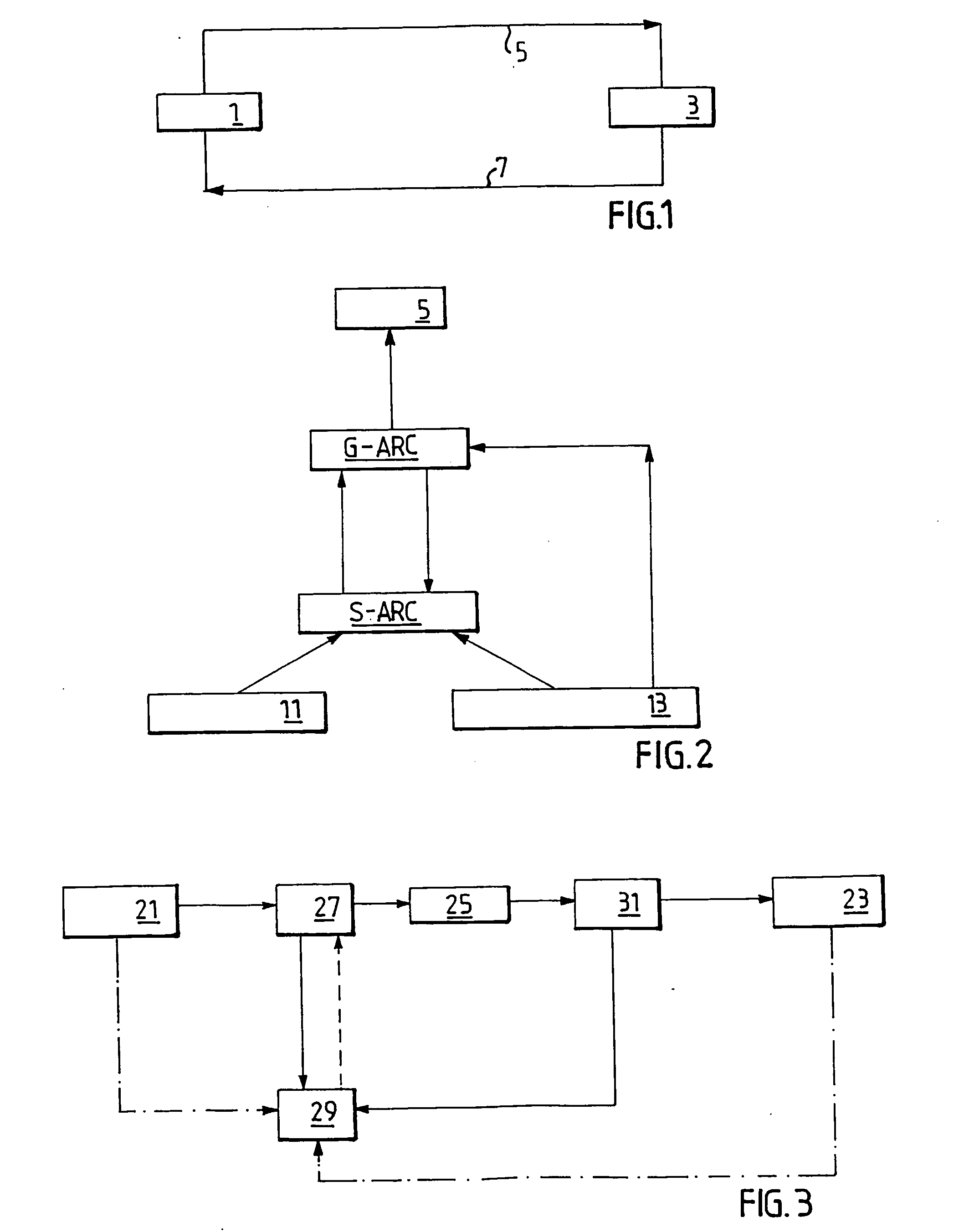
[0029]FIG. 1 illustrates, very simplified, the technical context of the invention. A sender, for example, a client terminal, 1 transmits data to a receiver 3 through a channel 5. The receiver may be, for example, a network server. The channel 5 constituting the access links and network enabling the sender 1 to send data to the receiver. Typically, each ARC sender / receiver pair will set up a communication link serving as a back-channel 7 for the ARC sender-receiver pair that forms the communication link in the opposite direction. The access links and network enabling the receiver to send data, such as acknowledgement of received data, to the sender is called a back-channel 7.

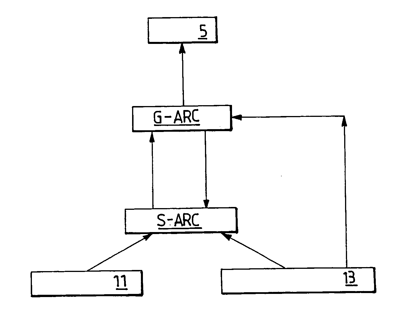
[0030]FIG. 2 provides a logical view of the invention showing the logical units and the exchange of control data. The logical functions Application, G-ARC and S-ARC may be distributed between the sending and the receiving units in many different ways. The arrangement for adaptive rate control comprises a generic...


PUM


Abstract

The present invention aims at enabling adaptive rate control, ARC, in a packet switched network, the ARC also being adapted to the requirements of a specific application. The arrangement for adaptive rate control of a connection between a sender and a receiver in a packet switched data network includes: A generic control elements for performing adaptive rate control according to a generic algorithm, the arrangement being characterized by at least one application specific control element, the application-specific control element being arranged to control the function of the generic control element in dependence of the characteristics of the application.

Description

TECHNICAL FIELD [0001] The present invention relates to a method for adaptive control of the transmission in a packet data network, as defined in the preamble of claim 1. The invention also relates to an apparatus for adaptive control of the transmission rate in a packet data network. BACKGROUND [0002] In packet data networks, a sender transmits digital packet data to one or more receivers through a network. The network may be, for example, an internet, following the Internet Protocol (IP) standard, and comprising IP routers and switches connected by digital communication links. The sender and the receiver are connected to the network by means of wireless or wireline access links using, for example, Asymmetric Digital Subscriber Line (ADSL), Public Switched Telephone Network (PSTN) modems, cable modems, General Packet Radio System (GPRS), Universal Mobile Telecommunication System (UMTS) or Edge access technologies. Communication protocols used include reliable protocols such as Tran...

Claims


Application Information

Patent Timeline
IPC IPC(8): H04L47/2416H04L47/2475
CPCH04L47/10H04L47/11H04L47/14H04L47/2416H04L47/2475H04L47/25H04W8/04
Inventor KARLSSON, ROLANDJANDEL, MAGNUS
Owner TERRAPLAY SYST AB
Why Eureka
Try Eureka