System and method for reading power meters

a power meter and system technology, applied in the direction of tariff metering equipment, sustainable buildings, measurement instrument housing, etc., can solve the problems of not being safe for people, subject to human error, labor-intensive process, etc., to reduce the amount of data, reduce the amount of transmission, and reduce the effect of its own energy consumption

Active Publication Date: 2005-10-06
BLUE LINE INNOVATIONS
View PDF21 Cites 95 Cited by
  • Summary
  • Abstract
  • Description
  • Claims
  • Application Information

AI Technical Summary

Benefits of technology

[0006] Advantageously, the detection unit provides one or more energy efficient features for reducing its own energy consumption. For instance, the detection unit can enter a sleep mode during certain time intervals while detecting the power consumption indicated by the power meter unit. Alternatively, or in addition, the detection unit can generate a prediction model that represents information related to the power consumption and transmit the prediction model parameters, rather than raw data, to the display unit which uses the prediction model parameters to show power consumption (this may be done in real-time). This reduces the amount of data that is transmitted to the display unit. This also reduces the amount of transmissions that are sent to the display unit since data need only be transmitted when the values of the prediction model parameters change.

Problems solved by technology

This process is labor intensive, can be subject to human error and in certain circumstances may not be safe for the person.
However, automatic power meter readers are generally limited to newer power meter installations.
Unfortunately, the operations that are carried out by the automatic power meter readers, such as detecting the rotation of the power meter disk and transmitting information related to power consumption of the structure are power hungry operations that would result in the frequent replacement of the batteries.
This is inefficient and cumbersome.
Another common issue for power utility companies is dealing with unsatisfied consumers who complain about their high electric bills.

Method used


Image

  • System and method for reading power meters
  • System and method for reading power meters
  • System and method for reading power meters

Examples


Embodiment Construction

[0030] In the following detailed description, numerous specific details are set forth in order to provide a thorough understanding of the invention. However, it will be understood by those of ordinary skill in the art that the invention may be practiced without these specific details. In other instances, well-known methods, procedures and components have not been described in detail so as not to obscure the invention.

[0031] Further, it will be appreciated that for simplicity and clarity of illustration, elements shown in the figures have not necessarily been drawn to scale. For example, the dimensions of some of the elements may be exaggerated relative to other elements for clarity. Further, where considered appropriate, reference numerals may be repeated among the figures to indicate corresponding or analogous elements.

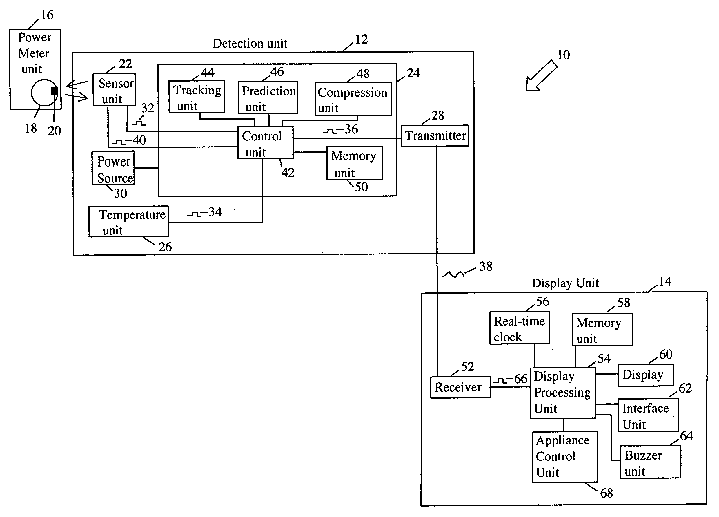
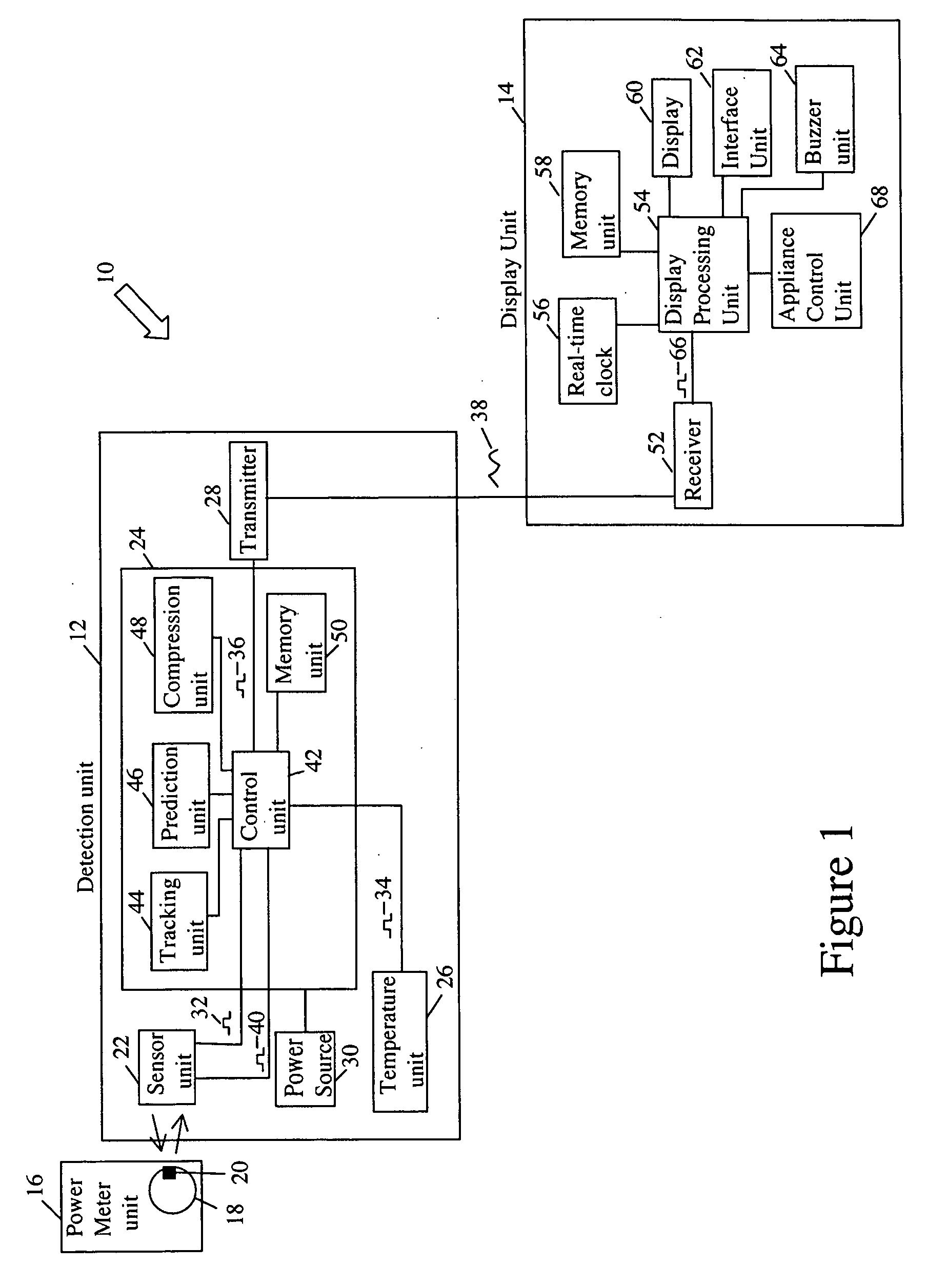
[0032] Referring first to FIG. 1, shown therein is a block diagram of an exemplary embodiment of a power meter reader system 10. The power meter reader system 10 c...


PUM


Abstract

A power meter reader system for automatically reading an indication on a power meter unit having a cyclical property that varies at a rate indicative of power consumption. The system comprises a detection unit that includes a sensor unit for monitoring the cyclical property of the indication and generating a consumption detection signal, a processing unit for generating an information signal based on data related to the consumption detection signal, and a transmitter for transmitting a transmission signal based on the information signal. The processing unit also generates a sensor enable signal to enable the sensor unit for only a portion of the cyclical property of the indication. The system further includes a display unit located remotely with respect to the detection unit for receiving the transmission signal and displaying the power consumption. The detection unit may also employ a prediction model for reducing power consumption in the detection unit.

Description

FIELD OF THE INVENTION [0001] The invention relates to a system and method for reading power meters. More particularly, the invention relates to a system and method for more efficiently reading power meters and providing an indication of power usage to a user of the power meter. BACKGROUND OF THE INVENTION [0002] Power meters are used by utility companies for measuring and providing a readout for the quantity of electricity that has been used in a commercial or residential establishment. Conventionally, if a person, such as a homeowner, wanted to monitor energy consumption, then the person would physically go outside to the location of the power meter to read the power meter. This process is labor intensive, can be subject to human error and in certain circumstances may not be safe for the person. Accordingly, there is a movement towards automatic power meter readers that integrate the capability of measuring the amount of electricity and communicating the measurement to the utility...

Claims


Application Information

Patent Timeline
Patent Type & Authority Applications(United States)
IPC IPC(8): G01R1/02G01R1/04G01R1/44G01R11/00G01R11/30G01R11/32G01R21/00G01R21/133
CPCY02B90/241Y04S20/32G01D4/008Y04S20/46G06Q50/06Y04S10/54G01R21/133Y02B90/20Y04S20/30G01D2204/18
Inventor TUFF, MAURICEGAGNON, STEPHAN
Owner BLUE LINE INNOVATIONS
Why Eureka
Try Eureka