

Barrier-protected container
a container and barrier technology, applied in the direction of axle-box lubrication, railway components, railway bodies, etc., can solve the problems of difficult or impossible to arrange reinforcement in the concrete in optimal configuration, extremely heavy encased structure,
- Summary
- Abstract
- Description
- Claims
- Application Information
AI Technical Summary
Benefits of technology
Problems solved by technology
Method used
Image

Examples
Embodiment Construction
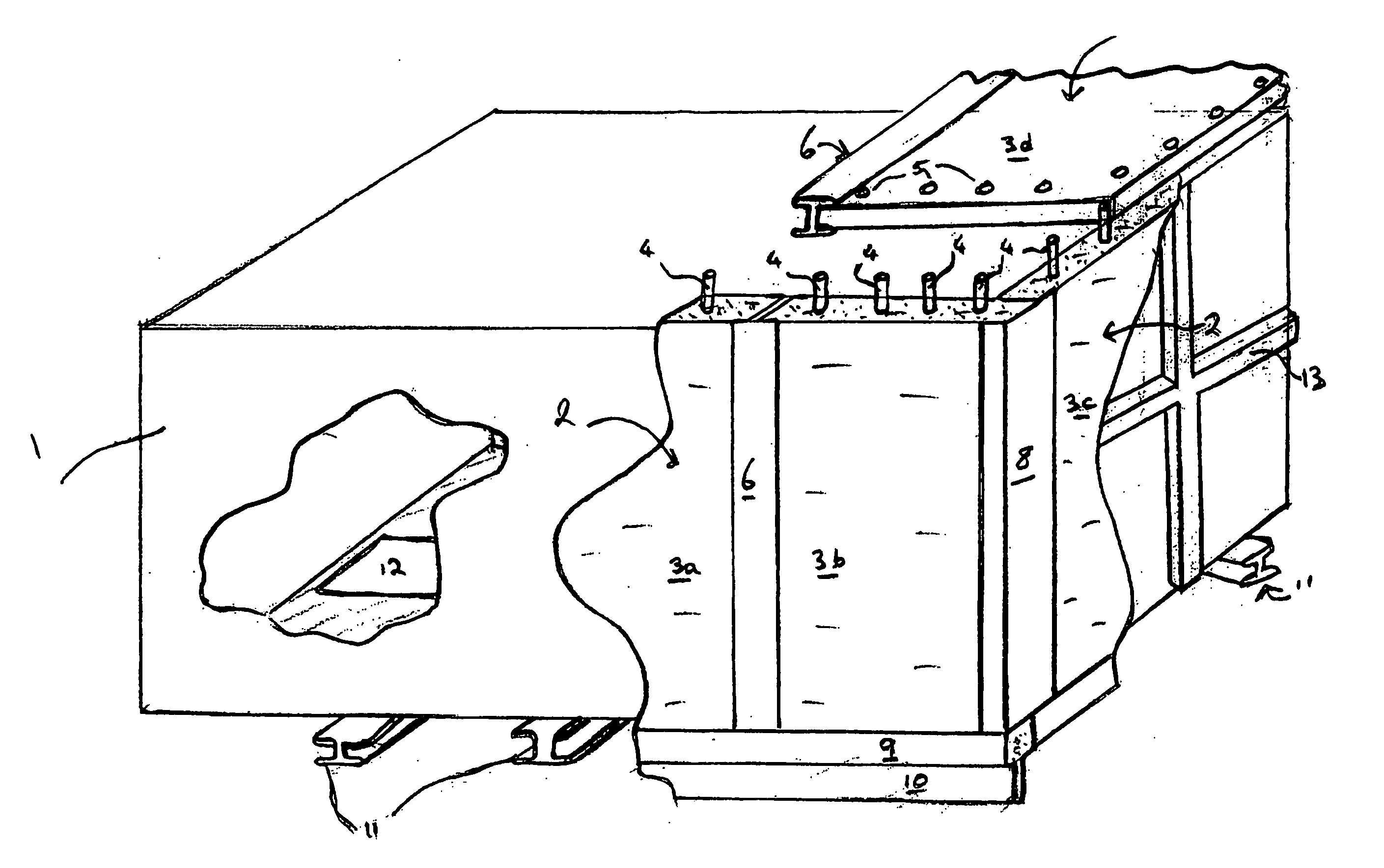
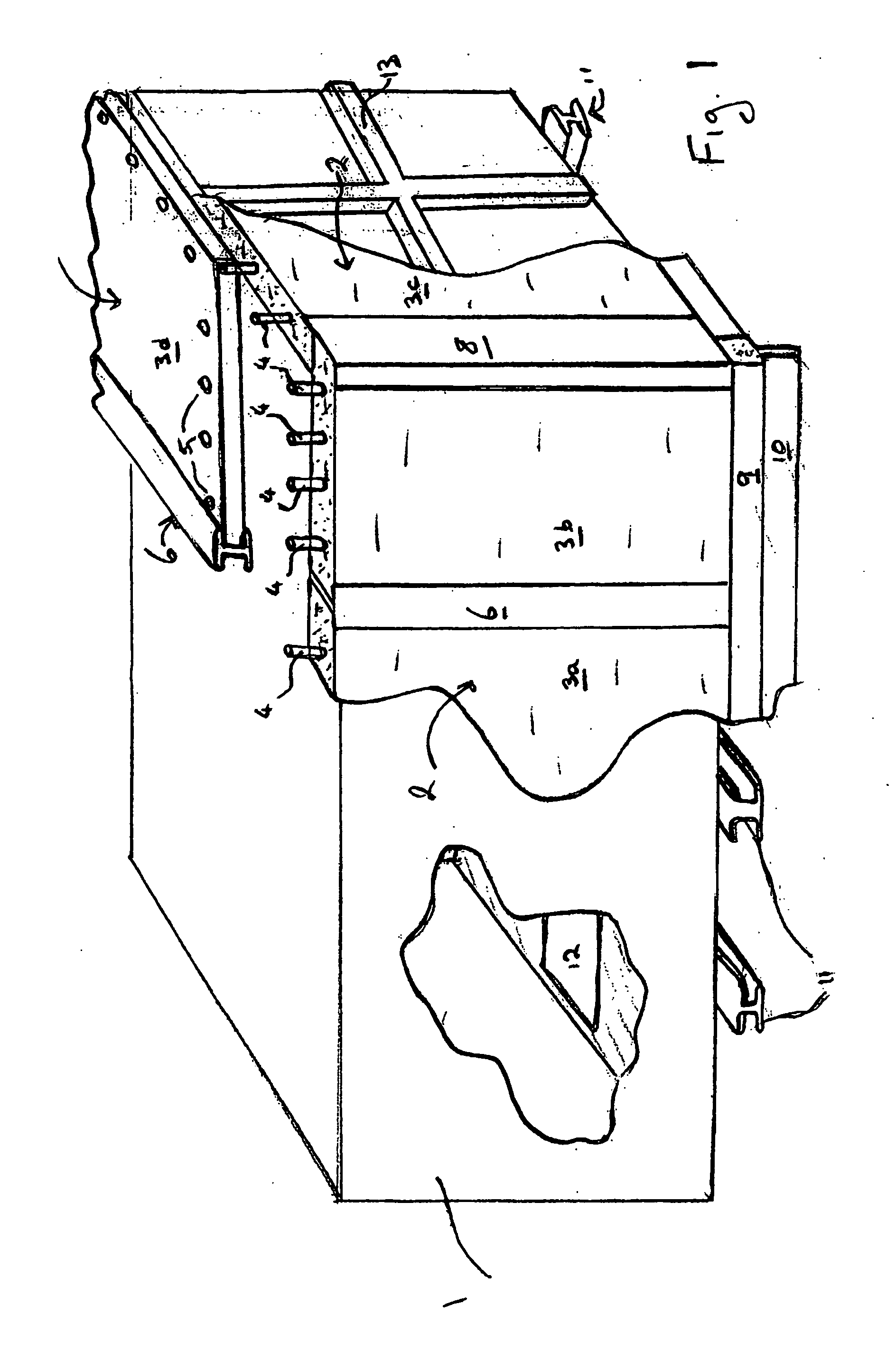
[0004] The present invention aims to provide an alternative type of blast and / or ballistic resistant structure which is more convenient, more reliable and lighter than concrete encased freight containers.
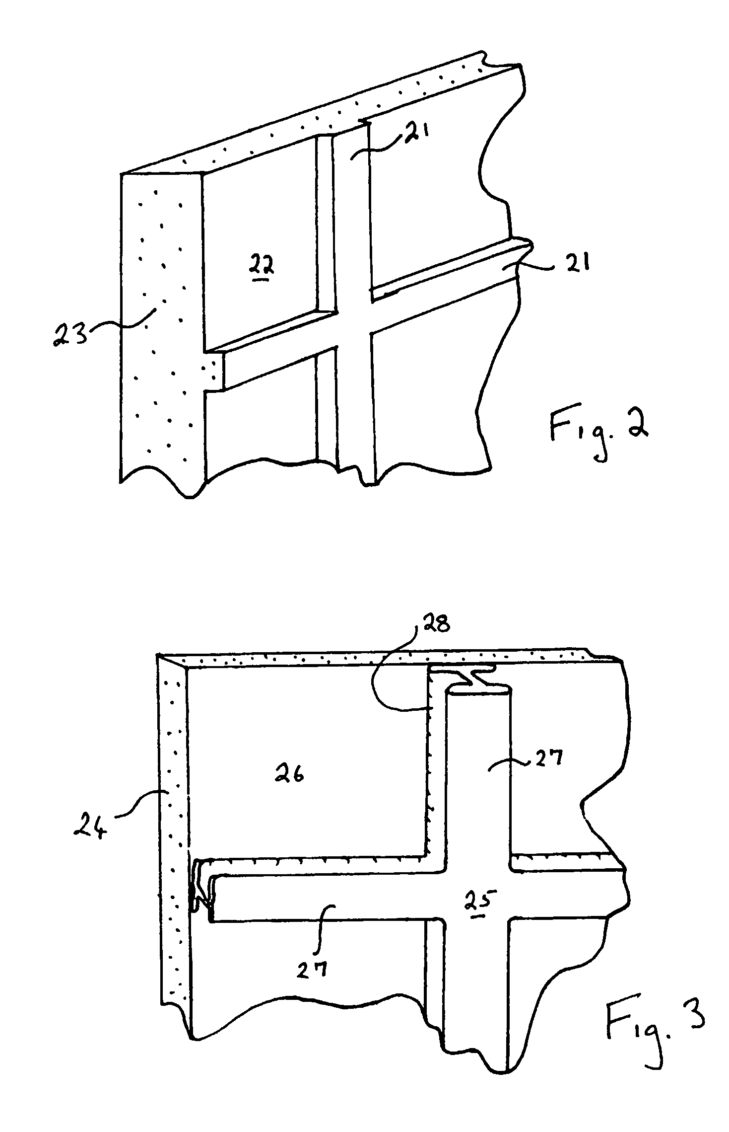
[0005] According to the invention, there is provided a structure comprising a walled freight container enclosing an interior volume of space, the container being at least partially clad internally and / or externally with a barrier structure, the barrier structure comprising a single panel or a plurality of panels of matrix material incorporating reinforcement elements, and means for human entry into and exit from the interior space of the container being located in a wall of the container and, if necessary for such entry and exit, also in the barrier structure.
[0006] As used herein, the terms “walled freight container” or freight container” or “shipping container” or “transport container” all refer to the reusable articles of transport equipment in common use for transporting goods...
PUM
 Abstract
Description
Claims
Application Information