Cyclonic separator with secondary vortex break

Active Publication Date: 2005-10-13
DRS SUSTAINMENT SYST
View PDF10 Cites 11 Cited by
  • Summary
  • Abstract
  • Description
  • Claims
  • Application Information

AI Technical Summary

Benefits of technology

[0016] Because of these and other problems in the art, described herein is a cyclonic separator which provides for a band pass separation of particles. That is, a cyclonic separator able to remove particles from an air stream that are greater than a predetermined minimum (which is greater than zero) while being smaller than a particular maximum. In an embodimen

Problems solved by technology

The transmission of agents is particularly of concern when used in aerosolized form where early detection may be difficult.
Because large buildings, subway systems, and the like utilize air circulation systems in relatively self contained environments there is increasing concern that the ventilation systems of these environments could be used in an attack to spread a dangerous warfare agent quickly and in a manner that is difficult to detect.
The inability to completely contain the agent has led to a plethora of searching devices to detect warfare agents as well as other potentially aerosolized substances released from the surface of an item.
One of the leading problems with aerosolized samples produced by these methods and even those produced through other actions, however, is that there is a large amount of air involved, even in a small application, and that air naturally includes a huge number of particles which are not of interest.
Pollens, dust, pollutants, atmospheric microorganisms and other materials are always in the air to be sampled, thus making detection of the particles of interest more challenging.
Uninteresting particles can clog the detector over time, increasing the amount of maintenance required or decreasing the detector's life.
Where each detector is provided the air flow sequentially, detection may be too slow and cumbersome, especially where large air flow volumes need to be monitored.
Further, depending on the type of detector, if too many uninteresting particles are present, detection of particles of interest could be

Method used


Image

  • Cyclonic separator with secondary vortex break
  • Cyclonic separator with secondary vortex break
  • Cyclonic separator with secondary vortex break

Examples


Embodiment Construction

)

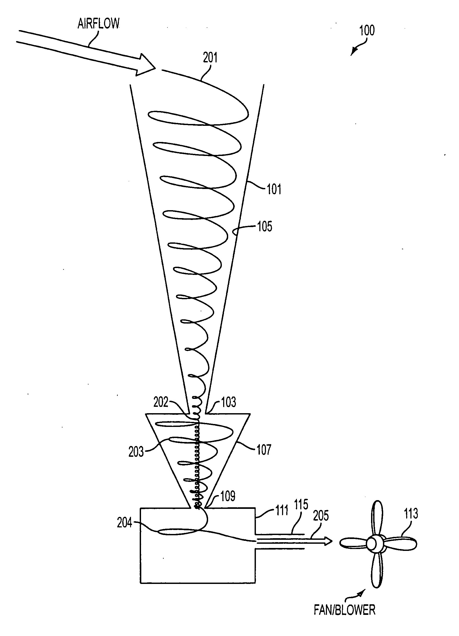
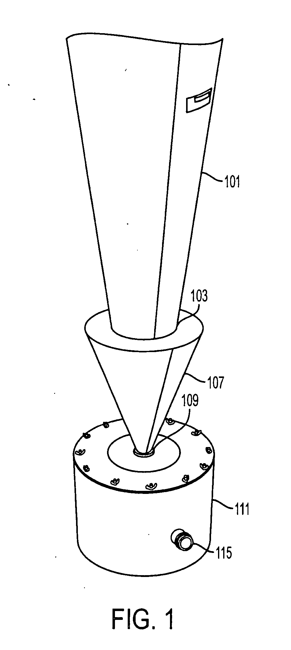
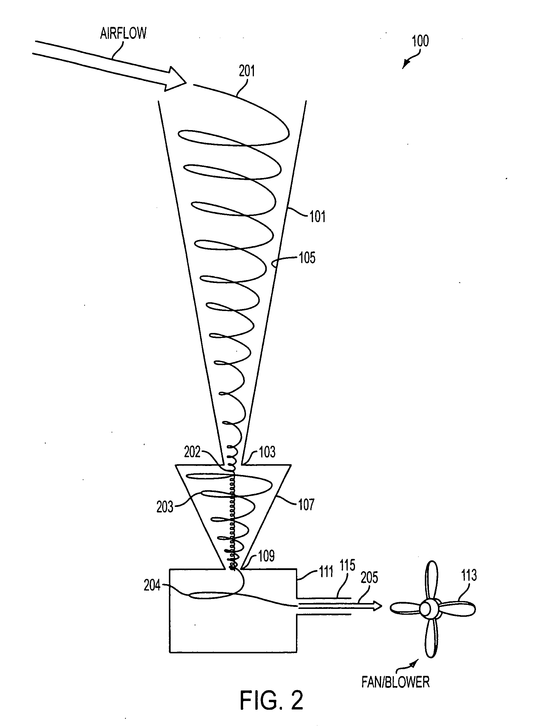
[0030]FIGS. 1 and 2 provide for different views of an embodiment of a cyclonic separator (100). The separator has three major components which in this embodiment are arranged vertically to each other. This arrangement provides a simple design for connection to related structures and other equipment, but the vertical orientation of the cyclone is not necessary to achieve proper performance. From the top to the bottom, a preferred embodiment includes a primary separator (101), a primary vortex break (107) and a secondary vortex break (111). While the preferred embodiment is arranged in this manner, the system can be rotated in space and still function. This arrangement, however, provides for benefits as gravity will help in the separation. Note that the sub-system comprised of the primary separator (101) and the primary vortex break (107) may, in an embodiment, be replaced by a primary separator (101) with no primary vortex break (107) being present. In an embodiment of the invention...


PUM

PropertyMeasurementUnit
Sizeaaaaaaaaaa
Sizeaaaaaaaaaa
Forceaaaaaaaaaa

Abstract

A cyclonic separator and methods of cyclonic separation which provide for a band pass separation of particles. That is, a cyclonic separator able to remove particles from an air stream that are greater than a predetermined minimum (which is greater than zero) while being smaller than a particular maximum. This band pass separation may be performed with the inclusion of a secondary vortex break on a cyclonic separator. Also discussed are cyclonic flow systems which provide for less deposition of aerosolized particles onto the cyclonic flow generator and related structures to improve likelihood of particles of interest being provided to an attached detector.

Description

CROSS REFERENCE TO RELATED APPLICATION(S) [0001] This Application claims the benefit of U.S. Provisional Patent Application Ser. No. 60 / 560,122, filed Apr. 7, 2004, the entire disclosure of which is herein incorporated by reference. BACKGROUND [0002] 1. Field of the Invention [0003] This disclosure relates to the field of cyclonic separators and the use of cyclonic flows to separate and isolate particles. In particular, this disclosure relates to the designs of cyclonic separator systems that allow particles in a particular size band to be collected and transferred to a separate flow as well as designs that lead to the reduction of particle buildup in the cyclonic flow generator and related components. [0004] 2. Background of the Invention [0005] The cyclonic separator is a well known general technology having applications from scientific research to today's bagless vacuum cleaners. The principle of operation is theoretically quite simple; the cyclonic separator uses rotational moti...

Claims


Application Information

Patent Timeline
IPC IPC(8): B01D45/12B04C3/00G01N1/22G01N15/02
CPCB01D45/12B04C3/00G01N1/2211G01N15/0255
Inventor BERTRAM, JEFFNELGNER, WILLIAM J.
Owner DRS SUSTAINMENT SYST
Why Eureka
Try Eureka