Gas turbine combustor, and gas turbine with the combustor

a technology of gas turbines and combustor tubes, which is applied in the direction of efficient propulsion technologies, machines/engines, lighting and heating apparatus, etc., can solve the problems that cannot be said to be fully capable of dealing with combustion vibration in a low-frequency area, and achieve the reduction of nox in exhaust gas, stable reduction of nox, and reduction of combustion vibration

Active Publication Date: 2005-10-13
MITSUBISHI POWER LTD
View PDF12 Cites 82 Cited by
  • Summary
  • Abstract
  • Description
  • Claims
  • Application Information

AI Technical Summary

Benefits of technology

[0010] It is an object of the present invention to provide a gas turbine combustor and a gas turbine that can reduce the combustion vibration in order to realize a decrease in NOx in a stable manner. Furthermore, it is another object to provide a gas turbine combustor and a gas turbine that can reduce the combustion vibration, irrespective of the frequency areas.
[0011] In order to achieve the above-mentioned object, a gas turbine combustor according to the present invention, comprising a cylinder body which has a combustion region therein, is provided with a first box body which is installed outside the cylinder body, forming a first internal space having a predetermined capacity; and a first throat having a predetermined length which has one end thereof open to the combustion region or a downstream area thereof and has the other end thereof open to the first internal space; and has a first resistive element having a multiple number of through-holes inserted and engaged into the one end of the first throat. By this, fluid particles serving as vibration elements of the combustion vibration that occurs in the combustion region are effectively trapped by the first resistive element; resonate with the air in the first internal space being connected through the first throat; and vibrate in the neighborhood of the first resistive element, damping the vibration amplitude thereof. In this way, it is possible to reduce the combustion vibration and realize a stable decrease in NOx. Here, the object to which one end of the first throat opens is a combustor basket or a transition piece which makes up the cylinder body or a bypass duct which is connected to a side wall of the cylinder body.
[0012] Additionally, in order to achieve the above-mentioned object, according to the present invention, a gas turbine combustor, comprising a cylinder body which has a combustion region therein, is provided with a box body which is installed outside the cylinder body, forming an internal space having a predetermined capacity; and a throat having a predetermined length which has one end thereof open to an area upstream of the combustion region and has the other end thereof open to the internal space; and has a resistive element having a multiple number of through-holes inserted and engaged into the one end of the throat. By this, fluid particles serving as vibration elements of the combustion vibration that occurs in a combustion region are effectively trapped by the resistive element; resonate with the air in the internal space of the box body being connected through the throat; and vibrate in the neighborhood of the resistive element, damping the vibration amplitude thereof. In this way, it is possible to reduce the combustion vibration and realize a stable decrease in NOx. Here, the object to which one end of the throat opens is a combustor basket which makes up the cylinder body or an outer shell which is installed so as to be concentric with the combustor basket.

Problems solved by technology

Therefore, it is effective to the combustion vibration in a high-frequency area, but at the same time, it cannot be said to thoroughly cope with the combustion vibration in a low-frequency area.

Method used


Image

  • Gas turbine combustor, and gas turbine with the combustor
  • Gas turbine combustor, and gas turbine with the combustor
  • Gas turbine combustor, and gas turbine with the combustor

Examples


first embodiment

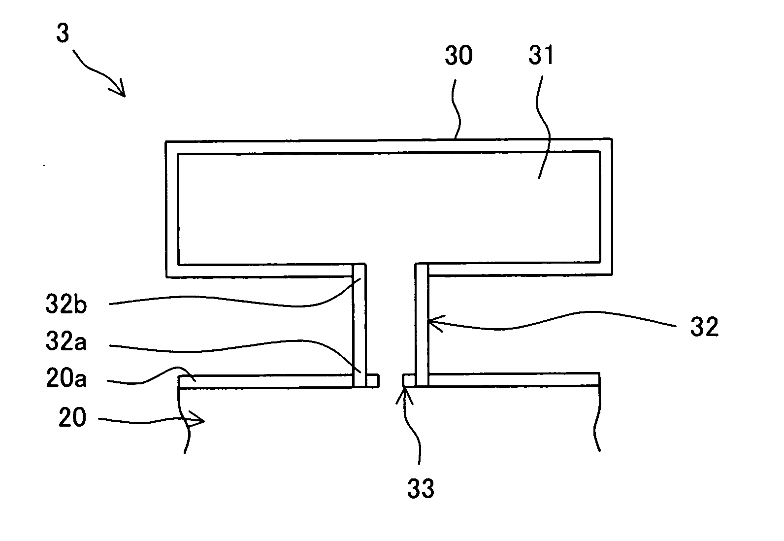
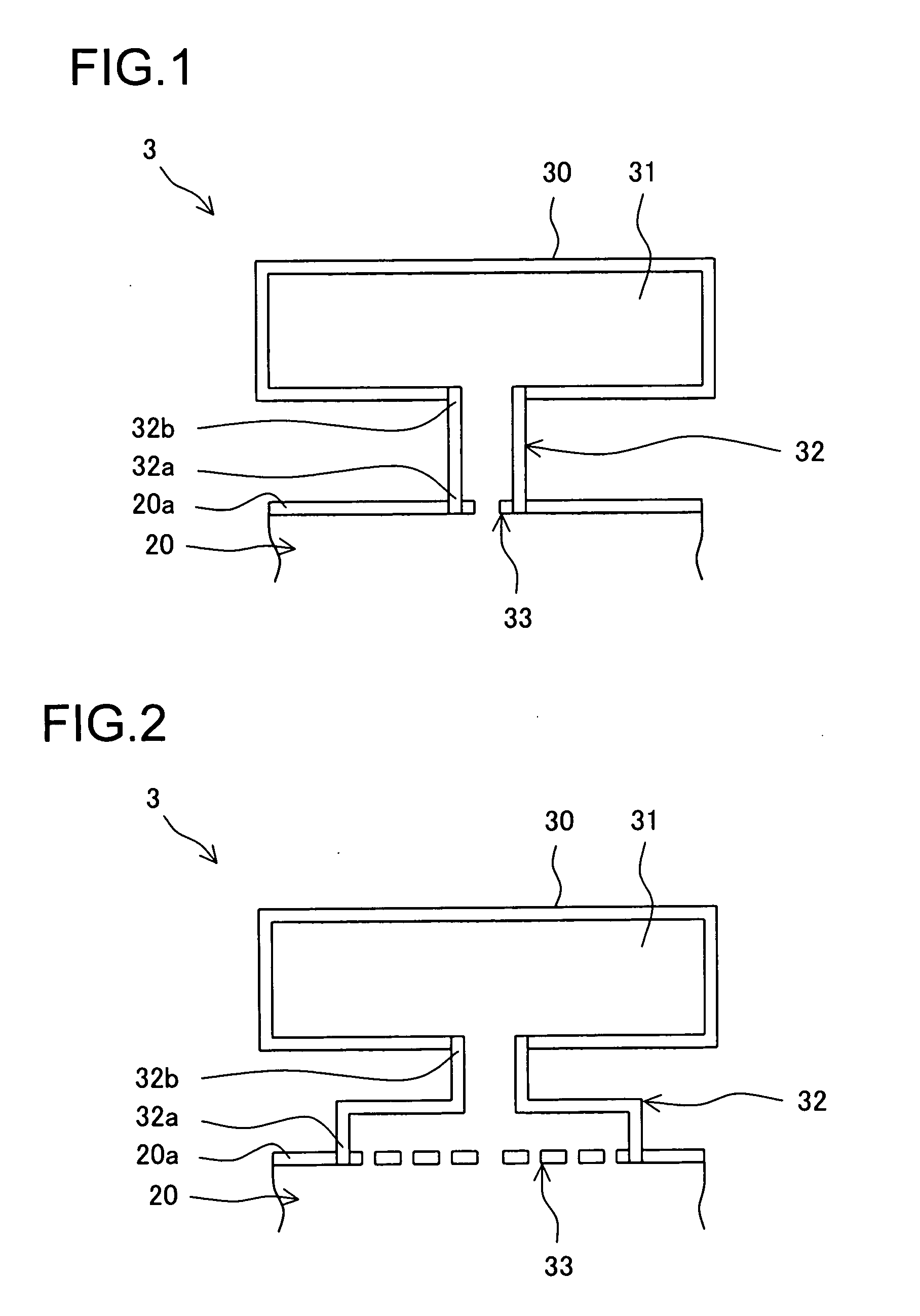
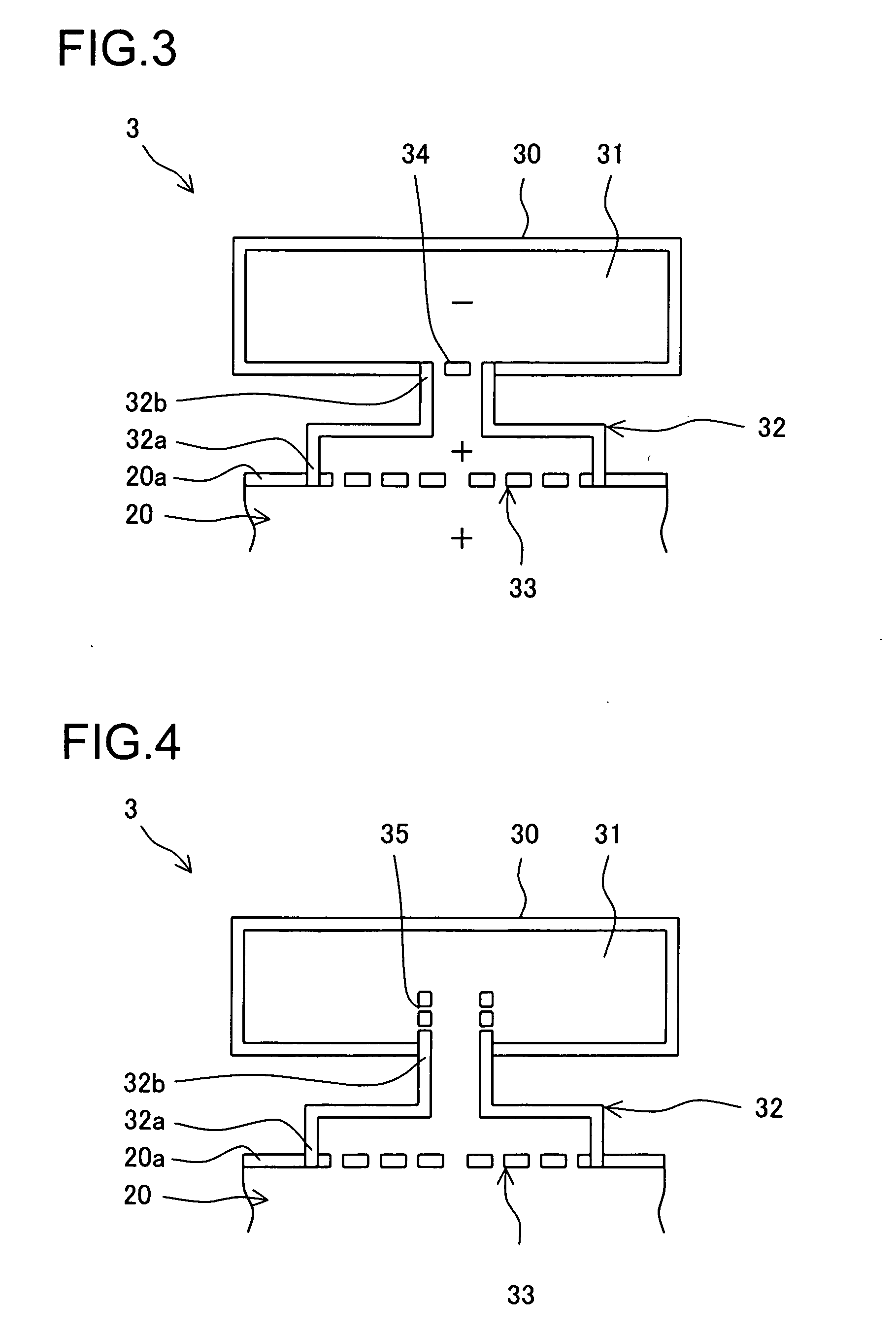
[0067] A combustor 3 in accordance with the present invention is applied to a gas turbine 1 shown in FIG. 47. As shown in FIG. 1, a first box body 30 is installed outside a side wall 20a of an object body 20, and a first internal space 31 having a predetermined capacity is formed by a cavity inside the first box body 30. Additionally, the first box body 30 is connected to the side wall 20a through a first tubular throat 32 having a predetermined length, and the first throat 32 has one end 32a open to the internal of the object body 20 from the side wall 20a and has the other end 32b open to the first internal space 31.

[0068] Further, a first resistive element 33 having a multiple number of through-holes is inserted and engaged into one end 32a of the first throat 32. The first resistive element 33 is, for example, a punching metal, a ceramic sintered metal or a sintered metallic mesh. In addition, the object body 20 mentioned herein is a cylinder body such as the combustor basket 6 ...

fourth embodiment

[0083] Here, in FIG. 5, a plurality of first box bodies 30 and the like (See FIG. 4) in accordance with the fourth embodiment are installed in parallel. At least one of the opening area or the length of each of the ends 32b of a first throat 32 and the capacity of each of first internal spaces 31 being formed by each of first box bodies 30, is mutually different. By this, vibration properties responding to each of first box bodies 30 and the like differ, so that it is possible to respond to various combustion vibrations in different frequency areas without fail.

[0084] Next, a sixth embodiment of the present invention will be described by referring to FIG. 6. Characteristic of a sixth embodiment is that further consideration is given to combustion vibration in a high-frequency area in the fifth embodiment. In a case of combustion vibration in a high-frequency area, wavelength is short. Therefore, a phase difference of pressure fluctuation occurs in the first internal space 31 itself ...

sixth embodiment

[0088] In other words, in accordance with the relevant embodiment, a protruding plate 37 having a multiple number of through-holes is installed, protruding through each of first internal spaces 31 so as to form a connecting passageway from an end 32b of the first throat 32. Constructed as this, because fluid particles effectively vibrate in each of through-holes of the protruding plate 37 due to same action of the resistive element 36 in accordance with the sixth embodiment, combustion vibration in a high-frequency area can thoroughly be reduced.

[0089] Next, an eighth embodiment of the present invention will be described by referring to FIG. 8. Characteristic of an eighth embodiment is that combustion vibration is reduced efficiently. Therefore, an eighth embodiment has an aspect that a plurality of first box bodies 30 and the like serving as major components of the first through seventh embodiments are installed as if they are installed in a row behind each other.

[0090] To put sim...


PUM


Abstract

In order to realize a stable decrease in NOx, a gas turbine combustor is supplied which can reduce combustion vibration. A combustor (3) is provided with a first box body (30), which is installed outside an object body (20) such as a combustor basket (6), a transition piece (7) or a bypass duct (11) so as to form a first internal space (31) having a predetermined capacity; and a first throat (32) having a predetermined length which has one end (32a) open to a side wall (20a) of the object body (20) and has the other end (32b) open to a first internal space (31); wherein, a first resistive element (33) having a multiple number of through-holes is inserted and engaged to one end (32a). Fluid particles serving as vibration elements of combustion vibration caused in a combustion region are effectively trapped by the first resistive element (33) and at the same time resonate with the air of the first internal space (31) being connected through the first throat (32) and vibrate in the neighborhood of the first resistive element (33), thereby damping vibration amplitude thereof.

Description

TECHNICAL FIELD [0001] The present invention relates to a gas turbine combustor (sometimes referred as a “combustor” hereinafter) and a gas turbine equipped with a gas turbine combustor, and especially, relates to a gas turbine combustor and a gas turbine that reduce combustion vibration in order to realize decrease in nitrogen oxides (NOx). BACKGROUND ART [0002] Conventionally, a gas turbine has an air compressor (sometimes referred as a “compressor” hereinafter), a combustor and a turbine serve as major components, wherein the combustor is installed between the compressor and the turbine that are directly connected to each other by a main shaft; an air serving as a working fluid is inhaled into the compressor by rotation of the main shaft and compressed therein; the compressed air is introduced into the combustor and burned with a fuel; and the high temperature and high pressure combustion gas is exhausted into a turbine so as to rotary-drive the main shaft with the turbine. The g...

Claims


Application Information

Patent Timeline
Patent Type & Authority Applications(United States)
IPC IPC(8): F23M20/00F23R3/04
CPCF05B2260/962F23R3/04F23R2900/00014Y02T50/675F23M20/005Y02T50/60
Inventor IKEDA, KAZUFUMIMANDAI, SHIGEMIKAWATA, YUTAKAAOYAMA, KUNIAKIONO, MASAKITANAKA, KATSUNORI
Owner MITSUBISHI POWER LTD
Why Eureka
Try Eureka