Regenerator and cryocooler using the same

Active Publication Date: 2005-10-13
LG ELECTRONICS INC
View PDF6 Cites 9 Cited by
  • Summary
  • Abstract
  • Description
  • Claims
  • Application Information

AI Technical Summary

Benefits of technology

[0010] Therefore, an object of the present invention is to provide a regenerator and a cryocooler using the same capable of improving regenerat

Problems solved by technology

However, the regenerator using the stainless lump or the mesh laminated body is very heavy.
In general, because the cooling part of the cryocooler comes into a cryogenic state in operation, lubricating oil freezes and thus cannot be used, and therefore a fluid bearing is used.

Method used


Image

  • Regenerator and cryocooler using the same
  • Regenerator and cryocooler using the same
  • Regenerator and cryocooler using the same

Examples


Embodiment Construction

[0019] Reference will now be made in detail to the preferred embodiments of the present invention, examples of which are illustrated in the accompanying drawings.

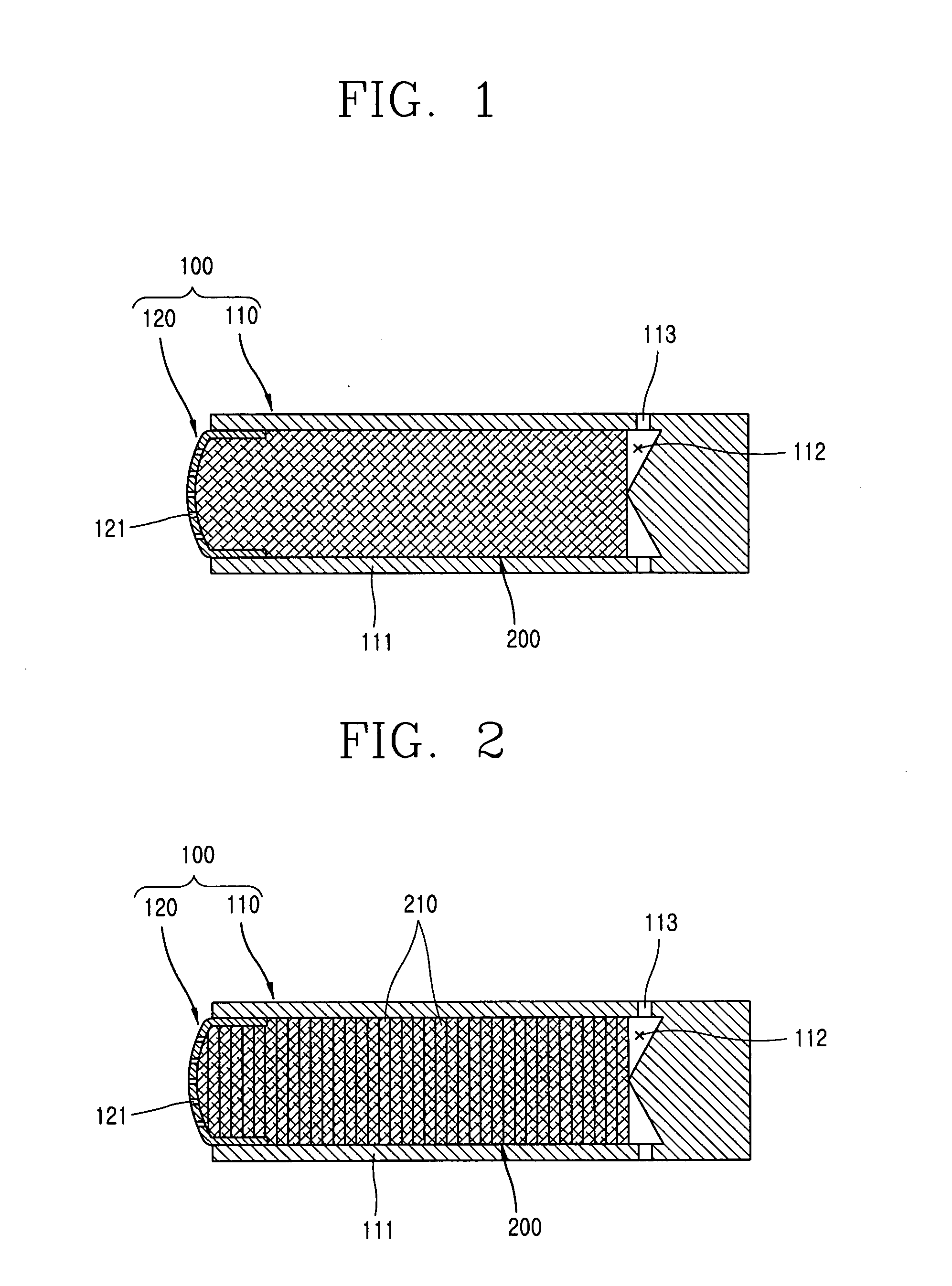
[0020]FIG. 1 is a sectional view showing one embodiment of a regenerator in accordance with the present invention.

[0021] As shown therein, the regenerator includes a casing 100 including a connection channel for making a high temperature part (not shown) and a cooling part (not shown) communicate; and a thermal energy storage material 200 inserted in the connection channel of the casing 100 and made of an aramid fiber absorbing and storing heat included in a working fluid flowing through the connection channel and radiating the stored heat to a working fluid.

[0022] The casing 100 includes an one side-closed type cylindrical case 110 having a cylindrical insertion groove 112 which is formed at one side of a cylindrical body 111 having a certain outer diameter and a length and has a predetermined inner diameter and a depth...


PUM


Abstract

A regenerator includes a casing including a connection channel for making a high temperature part and a cooling part communicate with each other; and a thermal energy storage material inserted in the connection channel of the casing and made of an aramid fiber which stores/radiates heat of a working fluid flowing through the connection channel. A cryocooler includes the regenerator. Accordingly, regeneration performance of storing heat included in the working fluid and transmitting the stored heat to a working fluid is improved, and simultaneously a weight is decreased, thereby minimizing abrasion of components.

Description

BACKGROUND OF THE INVENTION [0001] 1. Field of the Invention [0002] The present invention relates to a regenerator and a cryocooler using the same, and more particularly, to a regenerator and a cryocooler using the same capable of improving regeneration performance of storing heat included in a working fluid and transmitting the stored heat to the working fluid and of minimizing a weight. [0003] 2. Description of the Background Art [0004] In general, a cryocooler is mainly used to cool small electronic components, superconductors or the like. As the cryocooler, there are a Stirling cycle cooler, a pulse tube cooler and the like. [0005] The cryocooler includes a high temperature part for generating heat while compressing a working fluid by converting electrical energy into kinetic energy; and a cooling part rapidly cooled by a working fluid which is expanded by a pulse difference of the compressed operation and absorbs external heat. And, a channel through which a working fluid flows...

Claims


Application Information

Patent Timeline
IPC IPC(8): F25B9/14C09K5/08F25B9/00
CPCF25B9/14F25B2309/001F25B2309/003F25B2309/1415F25B9/00
Inventor KIM, SEON-YOUNG
Owner LG ELECTRONICS INC
Why Eureka
Try Eureka