
Device for portioned delivery of milk, particularly for cappuccino machines

a technology of cappuccino machine and milk delivery, which is applied in the field of cappuccino machine, can solve problems such as affecting storage, and achieve the effect of preventing the heating of milk in the connection line inside the refrigerator, reliable and efficient rinsing of this connection line, and ensuring storag

Active Publication Date: 2005-10-13
RANCILIO GROUP
View PDF3 Cites 30 Cited by
  • Summary
  • Abstract
  • Description
  • Claims
  • Application Information

AI Technical Summary

Benefits of technology

[0004] Because the connection part is connected via a second valve to an air source, the connection line and the delivery head may be completely emptied after the rinse procedure. Upon returning to operation, the delivery of blank portions of diluted milk may therefore be dispensed with. Because the first valve is connected on the outlet side only to the connection line, reliable and efficient rinsing of this connection line is achieved. Heating of the milk in the connection line inside the refrigerator is prevented.
[0005] The refinement according of having the first and second valves in the refrigerator has the advantage that the lines between the valves and the connection part on the connection lines may be kept short and hardly come into contact with milk.
[0006] The refinement of having a pump for an air source is advantageous above all if the refrigerator is positioned significantly below the delivery head.
[0007] The refinement of having a third valve positioned in the first line neighboring the rinsing agent source, outside the refrigerator is advantageous above all if the refrigerator is positioned spatially separated from the coffee machine and the rinsing agent, e.g., water, is also used for other purposes inside the machine, e.g., feeding a steam boiler.
[0008] By having a milk pump positioned upstream from the connection part is also used to overcome height differences and results in a more consistent foam if the delivery head is implemented as a milk foamer. In addition, it is used for portioning the milk.

Problems solved by technology

However, during the delivery of hot milk, steam may reach the cold region of the connection line via the double check valve and heat the milk in this region, which impairs its storability.

Method used


Image

  • Device for portioned delivery of milk, particularly for cappuccino machines

Examples


Embodiment Construction

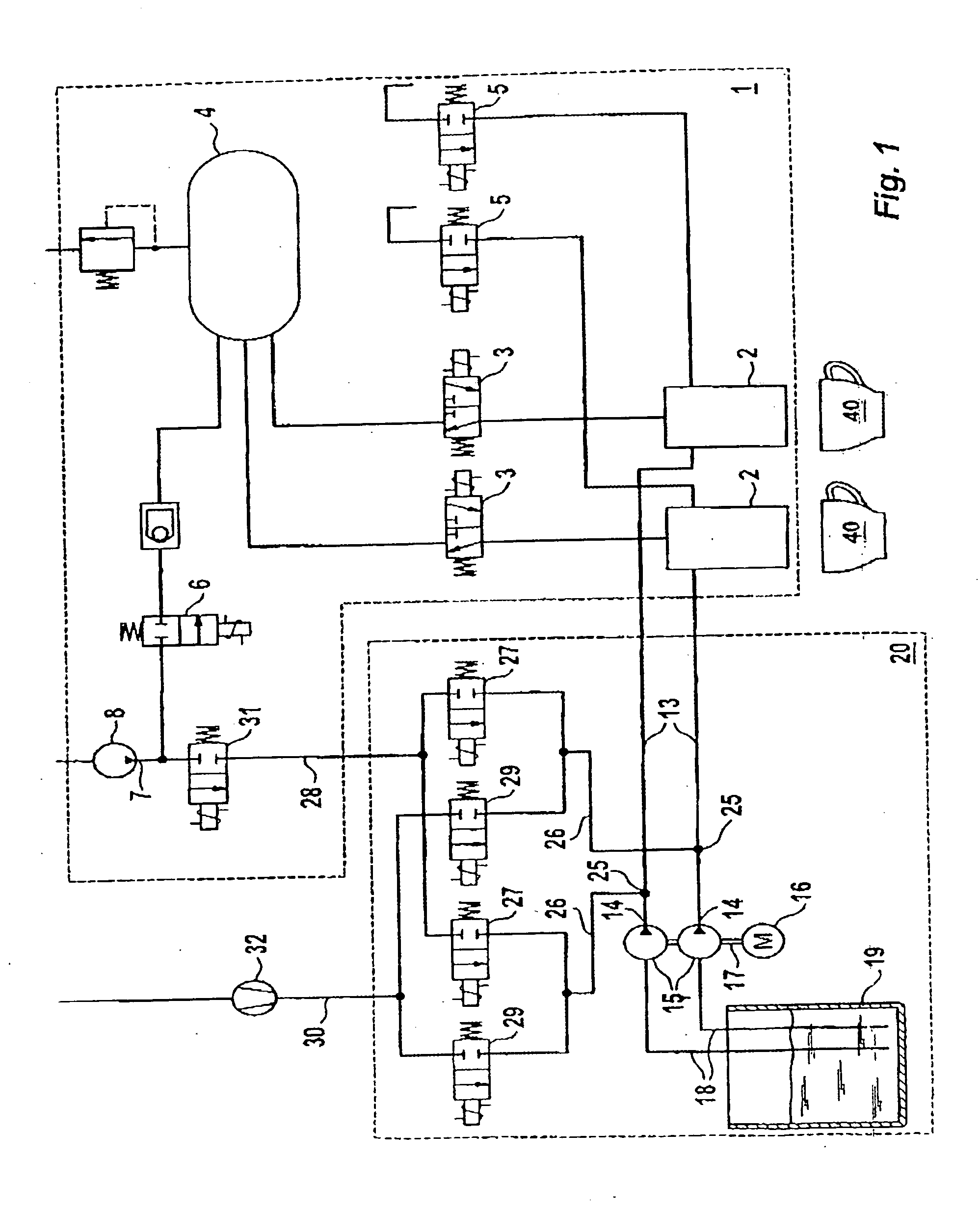
[0013] In the following, an exemplary embodiment of the present invention is described on the basis of the drawing. The single FIGURE shows a circuit diagram of a milk foaming device for cappuccino machines.

[0014] Two foamer heads 2 are positioned in a coffee machine 1. Each head 2 is connected via an on-off valve 3 to a steam boiler 4 and via a second on-off valve 5 to the atmosphere. A level switch (not shown) in the boiler 4 regulates the fresh water supply to the boiler 4 from the outlet 7 of a water pump 8 via a further on-off valve 6.

[0015] Each foamer head 2 is also connected via a connection line 13 to the outlet 14 of a volumetric milk pump 15. The two pumps 15 are driven by a shared motor 16, whose driven shaft 17 rotates around a predetermined angle of rotation to deliver a milk portion. The lines 18 to the suction side of the pumps 15 are dipped into a milk container 19. The container 19, the pumps 15, the lines 18, and a part of the lines 13 are installed in a refrige...


PUM


Abstract

A delivery head for delivering a milk portion is connected via a connection line to a milk container in a refrigerator. A rinsing agent source is connected via a first line to a connection part in the connection line. A first on-off valve is inserted in the first line. The connection part is also connected via a second line and a second valve to a fresh air source. The container, the valves, and the connection part are installed in a refrigerator. Through this implementation, complete emptying of the connection line and the delivery head of rinse water after the rinsing procedure, as well as efficient rinsing during the rinsing procedure, are achieved.

Description

BACKGROUND OF THE INVENTION [0001] The present invention relates to a device for portioned delivery of milk, particularly for cappuccino machines. Such a device is known from DE-OS 199 55 195 A1. This known device has a delivery head in the form of a milk mixing chamber, to which steam is supplied via a first valve, air is supplied via a second valve, and milk is supplied from a milk container via a pump and a double check valve. The milk container, the pump, and the check valve are positioned in a refrigerator. For cleaning the device, the steam supply line to the mixing chamber is connected via a further line to the double check valve. The steam supply line may also have cold water applied to it via a further valve. [0002] However, during the delivery of hot milk, steam may reach the cold region of the connection line via the double check valve and heat the milk in this region, which impairs its storability. The main part of the rinse water reaches the mixing chamber directly via ...

Claims


Application Information

Patent Timeline
IPC IPC(8): A23C9/00A47J31/46A47J31/40A01J3/00A47J31/44
CPCA47J31/4485A47J31/60A47J31/469
Inventor LANDOLT, MARKUS
Owner RANCILIO GROUP
Learn More