
Device and a method for sampling of milk

a sampling device and a technology for milk, applied in the field of devices and sampling methods for milk, can solve the problems of requiring a relatively large space for analysis devices, unnecessary drying process in order to remove such water or cleaning liquid from the passage, etc., and achieve the effect of effective rinsing process of the passage from milk residuals, quick and simple way

Inactive Publication Date: 2005-10-13
DELAVAL HLDG AB
View PDF12 Cites 21 Cited by
  • Summary
  • Abstract
  • Description
  • Claims
  • Application Information

AI Technical Summary

Benefits of technology

[0006] The object of the present invention is to provide a sampling device and a method, which provide reliable milk samples from individual animals without influences of possible milk residues stored in the conduit arrangement from previously milked animals.
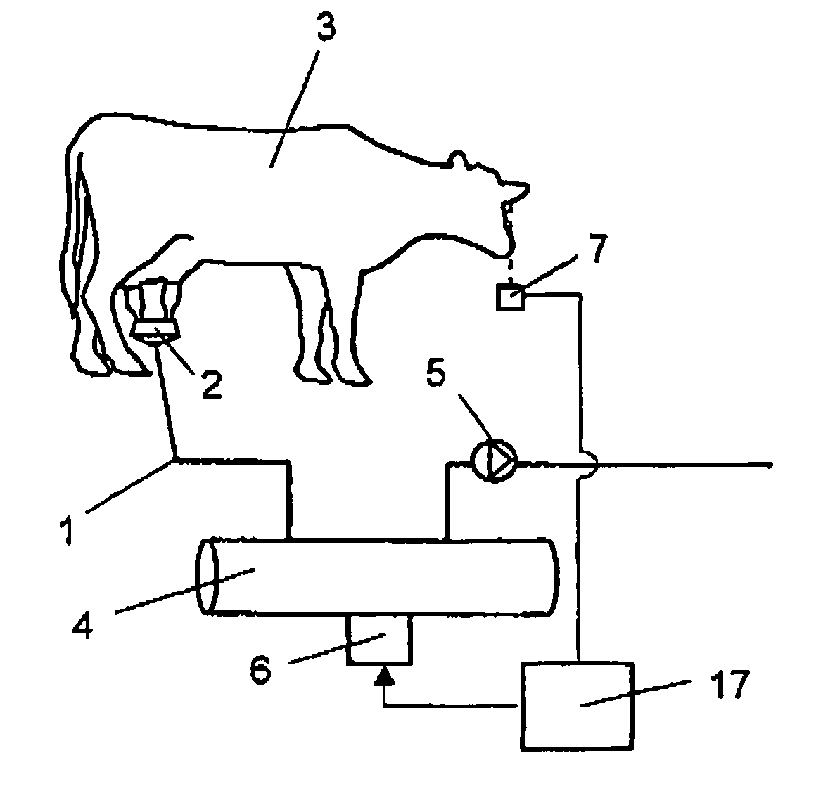
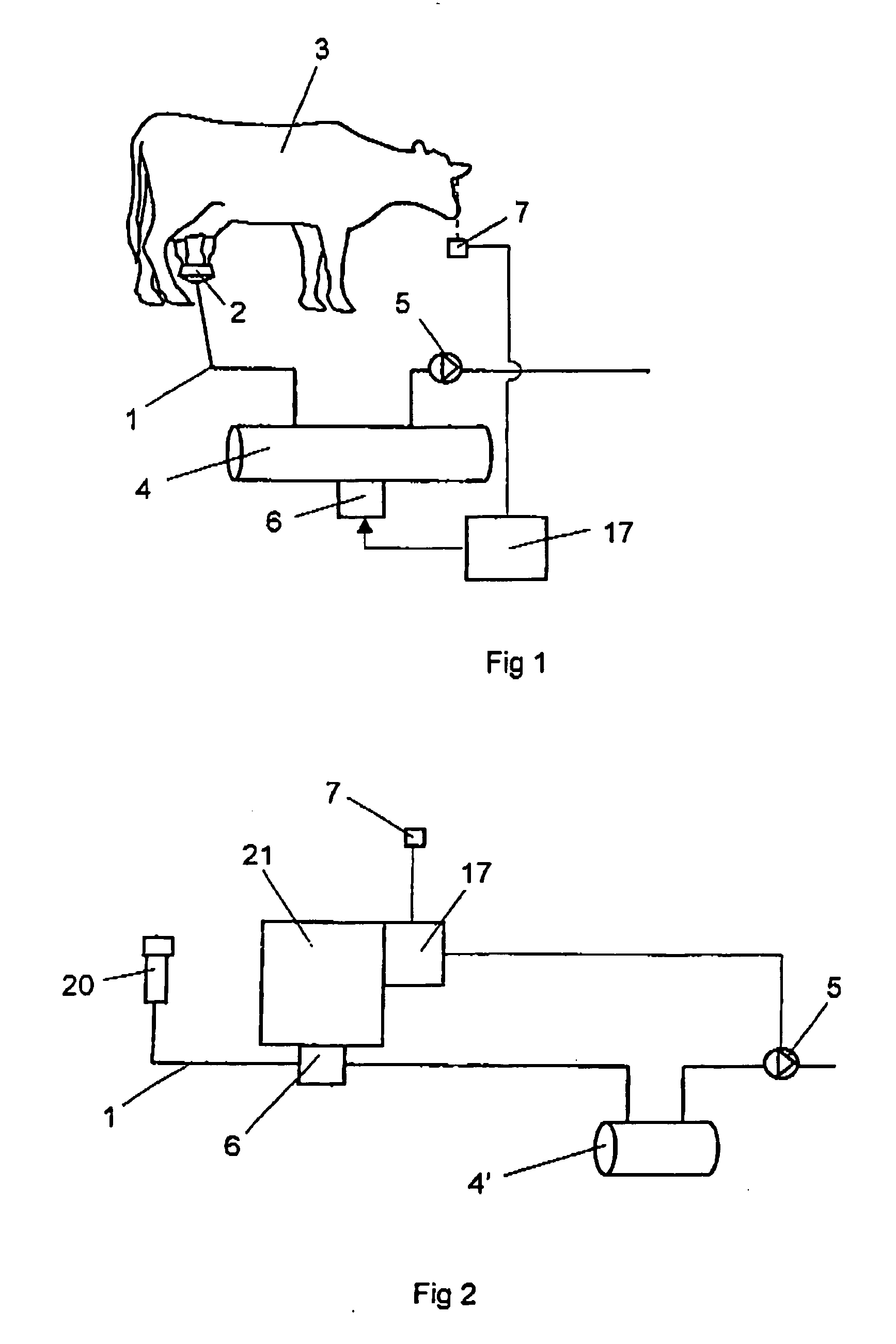
[0007] This object is achieved in that the device comprises flow means arranged to provide a flow of milk, from said animal, through at least a part of the passage at least a time period before a milk sample is taken in order to rinse at least said part of the passage from milk residues from a previously milked animal. Such a milk flow in the passage removes relatively quickly possible residues of milk from a previously milked animal in the conduit. Thereby, the risk that such milk residues will affect a milk sample of the milk from the milked animal is substantially eliminated. Such a rinsing process of the passage is very simple and it does not require a disconnection of the conduit arrangement from the milk line. The rinsing process does not remain any residue of water or another cleaning liquid into the conduit, which may affect the milk sample. Consequently, a drying process in order to remove such water or a cleaning liquid from the passage is also unnecessary. Hence, the rinsing process does not affect the milking process at all. The milk line may comprise a collecting container, wherein the passage is arranged to allow a milk flow from the collecting container to the collecting member. Such a temporarily collecting container may be used to store the milk in the milk line from the tested animal until the result of the sampling is obtained. If the milk quality is satisfactory, the milk is transported to a larger milk container collecting milk from several cows. If the milk quality is not satisfactory, the milk in the temporarily collecting container is discarded.
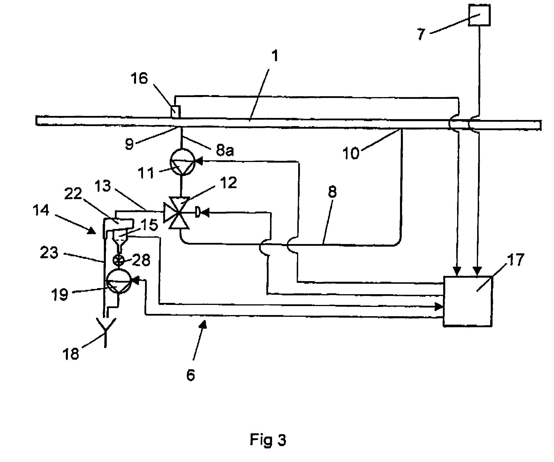
[0008] According to a preferred embodiment of the invention, the device comprises a conduit loop, having a first end connected to a milk line and a second end connected to the milk line at a distance from the first end, wherein at least a first part of the conduit loop, is comprised in said passage. An analysis device requires a relatively great deal of space. By using such a conduit loop, the length of the tube, which transports the milk samples to the analysis device, may be reduced. The second end of the conduit loop, which comprises an outlet opening, is thus connected to the milk line at a distance downstream of the first end, which comprises the inlet opening. Thereby, the milk, which has passed through the conduit loop, is prevented to return into the inlet opening. The milk flow through the conduit loop may rinse said first part of the conduit. Said milk is then guided back to the milk line. The rinsing process achieved by the milk from the animal, which is milked, is simple, quick, and effective.

Problems solved by technology

Consequently, a drying process in order to remove such water or a cleaning liquid from the passage is also unnecessary.
An analysis device requires a relatively great deal of space.

Method used


Image

  • Device and a method for sampling of milk
  • Device and a method for sampling of milk
  • Device and a method for sampling of milk

Examples


third embodiment

[0029]FIG. 3 shows a sampling device 6 according to the present invention. The sampling device 6 comprises a conduit loop 8 having an inlet opening at a first end 9, which is connected to the milk line 1, and an outlet opening at a second end 10. Thereby, a part of the milk, which flows in the milk line 1, is allowed to flow into the inlet opening at the first end 9 of the conduit loop 8. The milk in the conduit loop 8 is guided back to the milk line 1, via the outlet opening in the second end 10. Since the second end 10 is connected to the milk line 1 at a distance downstream of the first end 9, the milk, which has passed through the conduit loop 8, is prevented to return to the conduit loop 8. The conduit loop 8 has a substantially smaller inner cross-section area than the milk line 1. Thereby, only a relatively small amount of the milk, which flows in the milk line 1, is sucked into the conduit loop 8.

[0030] A pump 11 and a three-way valve 12 are arranged in the conduit loop 8. T...

fourth embodiment

[0036]FIG. 4 shows the device. When the three-way valve 12 here is in the first position, the gravitation and / or the pressure difference between the first end 9 and the second end 10 of the conduit loop 8 are arranged to provide a continuous milk flow in the conduit loop 8. This flow arises as soon as milk flows in the milk line 1 at the first end 9 of the conduit loop 8. Thereby, a quick and effective rinsing of milk residues from the previously milked cow is achieved in the first part 8a of the conduit loop 8. When a sample of the milk from the cow 3 is to be taken, the control unit 17 initiates an adjustment of the three-way valve 12 from the first position to the second position. The control unit 17 opens the valve 28 and activates the pump 19 in the analysing device 14. The milk in the first part 8a of the conduit loop 8 is now sucked into the second conduit 13 by the pump 19. The initial milk flow in the second conduit 13 streams through the analysing device 14 and out through...

fifth embodiment

[0038]FIG. 5 shows the device. In this case a valve 12′ is arranged in the milk line 1. The valve 12′ is arranged to allow a discharge of milk samples substantially direct from the milk line 1. The valve 12′ comprises a closeable opening 12″ located at a bottom surface of the milk line 1. An analysis device 14 is arranged in a position straight below said opening 12″ of the valve 12′. The control unit 17 is arranged to set the valve 12′ in an open position when a milk sample is to be taken. An air gap 24 is arranged between the valve 12′ and the analysis device 14. When a sample of the milk from a cow 3 is to be taken, the control unit 17 sets the valve 12′ in an open position. Thereby, a smaller part of the milk in the milk line 1 is discharged through said opening 12″ and into the delivery funnel 15 of the analysis device. The initially discharged milk flows through the delivery funnel 15 and out through the outlet conduit 18. The outlet conduit 18 may transport this milk back to ...


PUM

PropertyMeasurementUnit
diameteraaaaaaaaaa
thicknessaaaaaaaaaa
thicknessaaaaaaaaaa

Abstract

This invention relates to a device and a method for sampling of milk. The device includes a collecting member (15, 15′) arranged to receive milk samples from a milk line (1), which is arranged to transport milk from one animal (3) at a time, and a passage (8a, 12″, 13) arranged to allow a milk flow from the milk line (1) to the collecting member (15, 15′). The device comprises flow means (11, 19) arranged to provide a milk flow, from the animal (3), through at least a part of the passage (8a, 12″, 13) at least a time period before a milk sample is to be taken in order to rinse at least the part of the passage (8a, 12″, 13) from milk residues from a previously milked animal.

Description

THE BACKGROUND OF THE INVENTION AND PRIOR ART [0001] The present invention relates to a device and a method for sampling of milk from an animal the milk of which is to be tested, wherein the device comprises a collecting member arranged to receive milk samples from a milk line, which is arranged to transport milk from one animal at a time, and a passage arranged to allow a milk flow from a milk line to the collecting member. [0002] Sampling of milk is performed in order to analyse the quality of the milk. Thereby, the content of particular substances and the existent of bacterium in the milk of individual cows may be analysed. Usually, tubes having a relative small inner diameter are used for delivering milk samples from a milk line to a milk analysing device. Inevitably, milk residues from previous samplings are stored as a thin film along the inner walls of such tubes. Thereby, the amount of milk forming this film is not negligible in relation to the whole amount of milk in a samp...

Claims


Application Information

Patent Timeline
Patent Type & Authority Applications(United States)
IPC IPC(8): A01J5/01A01J5/04G01N1/20G01N33/04
CPCA01J5/01A01J5/0131A01J5/0132A01J5/045G01N1/2035G01N33/04G01N2001/205
Inventor BOSMA, EPKEHOLMERTZ, NILS ERIK
Owner DELAVAL HLDG AB
Learn More