Compensation reservoir for a cooling circuit of an internal combustion engine

a technology of internal combustion engine and cooling circuit, which is applied in the direction of liquid cooling, engine components, machines/engines, etc., can solve the problems of no longer ensuring that the coolant exiting the coolant pipe still discharges below or at the liquid level, and the risk of additional foam formation, so as to increase the viscosity of the liquid, reduce the kinetic energy of the inflowing water/gas mixture, and increase the kinetic energy of the inflowing coolant.

Inactive Publication Date: 2005-10-13
DR ING H C F PORSCHE AG
View PDF3 Cites 32 Cited by
  • Summary
  • Abstract
  • Description
  • Claims
  • Application Information

AI Technical Summary

Benefits of technology

[0005] The arrangement of the coolant pipes in the compensating tank is adjusted to the liquid level in the compensating tank so that, normally, the coolant pipes discharge at or below the liquid level. This prevents foaming essentially because the higher viscosity of the liquid in the compensating tank effectively decreases the kinetic energy of the inflowing water / gas mixture. Particularly during uphill or downhill driving, however, it is no longer ensured that the coolant exiting from the coolant pipes still discharges below or at the liquid level. In this case the curved guiding walls provided in the compensating tank ensure that the kinetic energy of the inflowing coolant is continuously decreased such that foaming is largely avoided even in these driving situations.

Problems solved by technology

The coolant flowing out of the coolant pipe first strikes an end face of the trough, however, so that there is a risk of additional foam formation.
Particularly during uphill or downhill driving, however, it is no longer ensured that the coolant exiting from the coolant pipes still discharges below or at the liquid level.

Method used


Image

  • Compensation reservoir for a cooling circuit of an internal combustion engine
  • Compensation reservoir for a cooling circuit of an internal combustion engine
  • Compensation reservoir for a cooling circuit of an internal combustion engine

Examples


Embodiment Construction

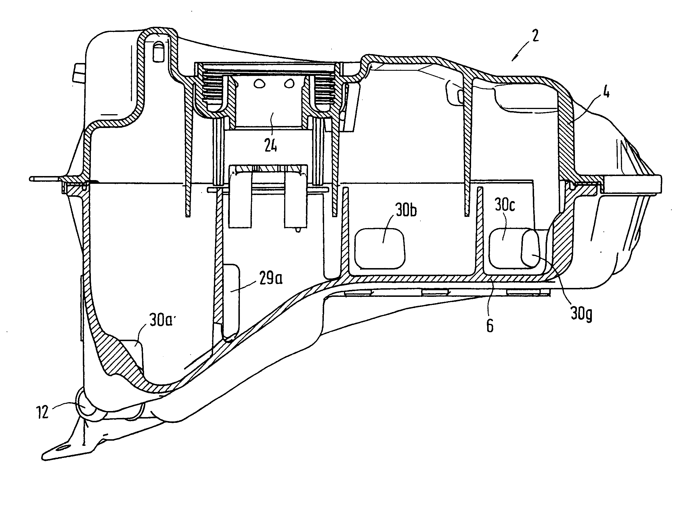
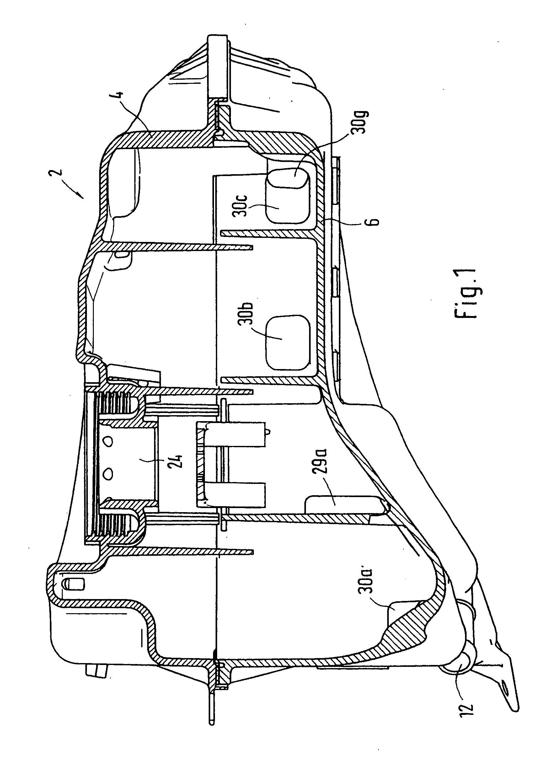
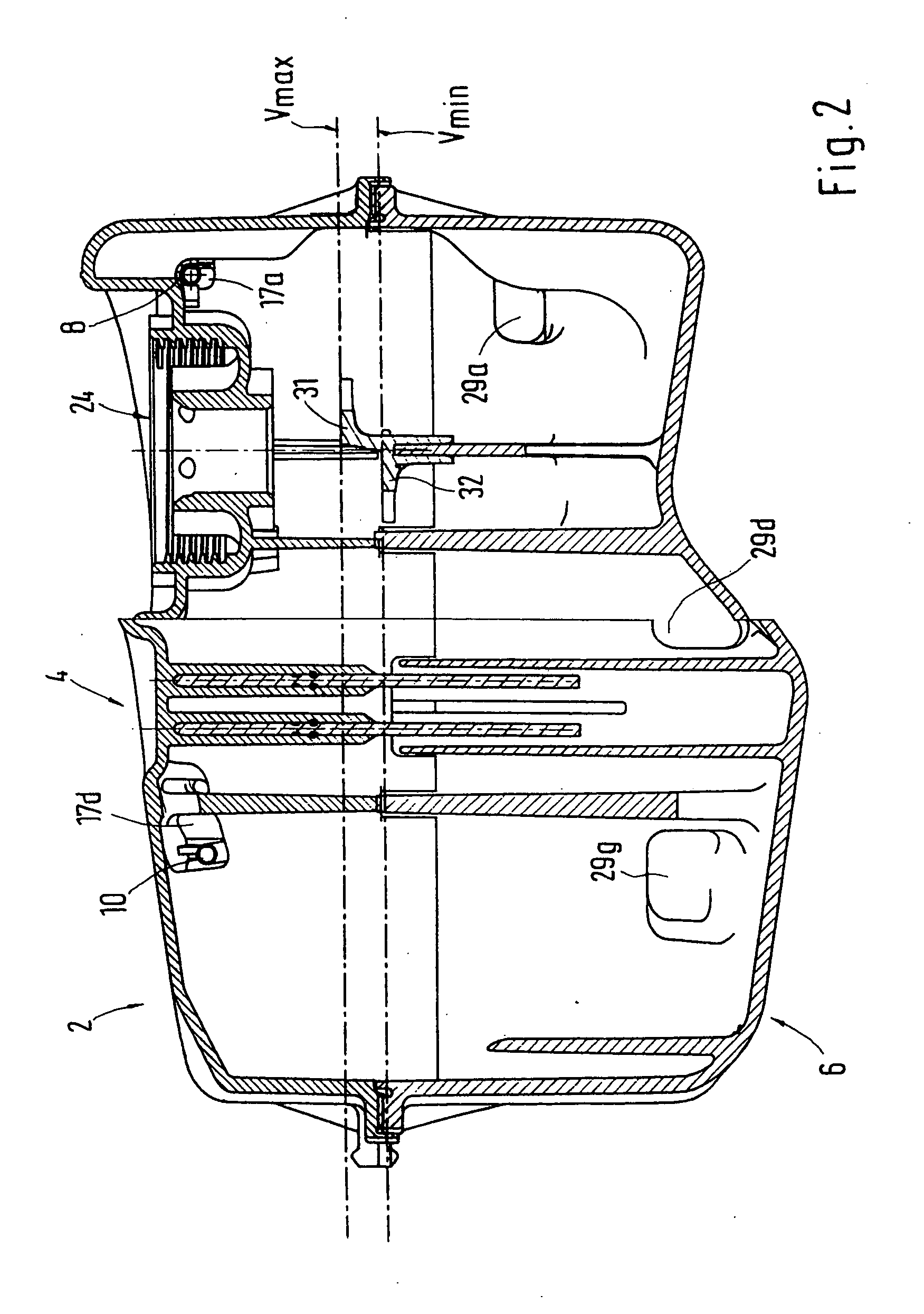
[0017] The compensating tank 2 integrated into the cooling circuit of an internal combustion engine has an upper shell 4 and a lower shell 6, which are joined, for example, by vibration welding. The coolant flows into the compensating tank 2 through two pipes integrated in the upper shell 4, hereinafter referred to as coolant pipes 8 and 10. The return flow or outlet 12 is formed in the lower shell 6. Both the upper and the lower shell 4, 6, have a chamber system, which will now be described in greater detail. In the upper shell 4, in the present example, there are twelve chambers 14a to 14l, which are formed by transverse and longitudinal walls 15a to 15i and 16a to 16h rising from the bottom of the upper shell 4. The two coolant pipes 8 and 10 introduced into the upper shell 4 are guided through openings 17a to 17c and, respectively, 17d to 17f made in the transverse walls 15a to 15c and, respectively, 15g to 15i up to the two rearmost chambers 14d and 141. The openings 17a to 17c...


PUM


Abstract

A compensating tank for a cooling circuit of an internal combustion engine has at least one inflow connection and one outflow connection, both of which are connected with the cooling circuit, a chamber system formed in the tank to receive the coolant, such that the individual chambers are at least partially interconnected via openings, and a coolant pipe connected with the inflow connection discharging into one of the chambers in which an impact element is provided for the inflowing coolant. The impact element is configured as a curved guiding wall along which the inflowing coolant is specifically guided. This inhibits, among other things, foaming of the coolant flowing into the compensating tank.

Description

BACKGROUND AND SUMMARY OF THE INVENTION [0001] This invention relates to a compensating tank for a cooling circuit of an internal combustion engine. [0002] German Laid Open Document DE 100 21 180 A1 discloses a compensating tank of a cooling circuit of an internal combustion engine in which means are provided to reduce foaming of the coolant introduced into the compensating tank. For this purpose, the coolant is introduced via a coolant pipe into a chamber of the tank where it initially meets a U-shaped trough provided in the chamber through which the coolant can drain into the coolant reservoir after overcoming the overflow edge of the trough. The coolant flowing out of the coolant pipe first strikes an end face of the trough, however, so that there is a risk of additional foam formation. German Laid Open Document DE 40 35 284 A1 describes a compensating tank in which a coolant pipe discharges into the compensating tank below the liquid level. [0003] Thus, an object of the inventio...

Claims


Application Information

Patent Timeline
Patent Type & Authority Applications(United States)
IPC IPC(8): F01P11/02
CPCF01P11/028F01P11/029
Inventor KASTELL, DIRKZAREMBA, DIETER
Owner DR ING H C F PORSCHE AG
Why Eureka
Try Eureka